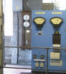
Fernando_g’s interest in measuring the frequency of his local mains supply piqued my interest in knowing how well our own mains frequency was maintained.
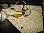
Way back in 2007, I’d built a timer devised by Hippy which incorporated an 08M picaxe and a 32kHz crystal. It worked well at the time but in recent years, it had found its way into my junk box. I thought that this module could form the basis of a quite accurate mains frequency monitor if its 32k crystal oscillator could time 50 mains pulses and report its count.
So I built a simple mains interface incorporating:-
• A 9 volt AC plugpack
• A full bridge rectifier, smoothing capacitor and resistor divider to bring the rectified DC voltage down into the 5 volt range.
• and a diode connected before the bridge rectifier to supply base current to a transistor so as to square up the sin wave into an asymmetric square wave.
The smoothed DC, resistor divided supply voltage was fed to pin c.2 while the square wave was connected to pin 1 of the 08M2 which would replace the 08M that was originally installed in Hippy’s timer module.
The following program was externally programmed into the 08M2 as it cannot be programmed in the timer module because the normal “serial in” pin forms part of the 32k oscillator. I’ve included Hippy’s original circuit diagram into this program for information. My part of the program also owes much to the efforts of Hippy, Jeremy Leach & others for a timer program also written about that time which used Timer1 to time the length of pause commands .
Code:
; *****************************************************************************
; *                                                                           *
; *     Hippy's Circuit Diagram for 08M Timer module                                                       *
; *                                                                           *
; *****************************************************************************

;              .----------------------------------.
;       TX O<--'        ___                       |
;       RX O-------.---|___|---.--|>|-- +V        |
;       0V O--.   .|.   22K    |                  |
;             |   | |          |                  |
;             |   |_| 10K      |                  |
;            _|_  _|_          |                  |
;                              |    PICAXE-08M    |
;       32.768kHz XTAL         |   .----------.   |
;        _______               |   | +V    0V |   |
;       |       |----.---------|---| SI    O0 |---'  Plaintext Out    4800 baud
;       |_______|----|----.----|---| X4    X1 |--->  Binary Out       4800 baud
;                   _|_  _|_   `-->| I3    X2 |--->  Square Wave Out  0.5Hz
;         2 x 33pF  -.-  -.-       `----------'
;                   _|_  _|_
;
;       Note that the PICAXE-08M must be programmed out of circuit as it is
;       not possible to program the 08M in-circuit in this configuration.


#picaxe 08M2
#no_data

Symbol T1CON = b0
Symbol T1ConOff=b1
Symbol Timer1ValueW = w1
Symbol Volt = w2
Symbol AccVolt = w3
Symbol Temp=b8

Symbol RAM_T1CON = $18
Symbol RAM_TMR1 = $16


'T1CON:
Symbol TMR1CSH_Bit = bit7	'Timer1 Clock Source Select bits
Symbol TMR1CSL_Bit = bit6	'Timer1 Clock Source Select bits
Symbol T1CKPS1_BIT = bit5	'Timer1 Input Clock Prescale Select bits
Symbol T1CKPS0_BIT = bit4	'Timer1 Input Clock Prescale Select bits
Symbol T1OSCEN_BIT = bit3	'LP Oscillator Enable Control bit
Symbol T1SYNC_BIT = bit2	'Timer1 External Clock Input Synchronization Control bit
Symbol Unimplemented_BIT = bit1
Symbol TMR1ON_BIT = bit0	'Timer1 On bit;1 = Enables Timer1;0 = Stops Timer1 Clears Timer1 Gate flip-flop

Initialise:
	SetFreq M32
	Gosub InitialiseTimer1

Main:
pause 4000	'wait 0.5 secs

do
	AccVolt=0					'Initialize cumulative voltage count
	do: loop until pinc.1=0	'Wait for positive part of waveform to end
	do: loop until pinc.1=1	'Wait for negative part of waveform to end
	Gosub ResetAndStartTimer1	'Start the clock
	For Temp=1 to 50				'Repeat for the next 50 cycles
		do: loop until pinc.1=0
		readadc10 c.2,Volt		'Read the resistor divided DC voltage on the capacitor
		AccVolt=AccVolt+Volt		'and accumulate it
		do: loop until pinc.1=1
	next Temp
	Gosub GetTime					'Stop the clock and read the timer
	Volt=AccVolt/5					'Divide by 50 & multiply by 10
	Volt=Volt**31360				'Convertion factor based on transformer voltage & resistor divider

	sertxd (#Volt,", ",#Timer1ValueW,CR,LF)	'Print Mains voltage*10 and Timer Value
loop														'Freq=50*2^15/Timer Value (done in Excel)

	'------------------------------------------------------------------------------------------
InitialiseTimer1:
	'Sets the T1CON control register. Only needs to be called once, before
	'using Timer1.

	Peeksfr RAM_T1CON,T1CON

	TMR1CSH_Bit =1	'Timer1 clock source is 32k crystall oscillator
	TMR1CSL_BIT = 0	'Timer1 clock source is 32k crystall oscillator
	T1CKPS1_BIT = 0	'Divide by 1 Pre-Scaler
	T1CKPS0_BIT = 0	'Divide by  Pre-Scaler
	T1OSCEN_BIT = 1	'Dedicated Timer1 oscillator circuit enabled
	T1SYNC_BIT = 0		'Synchronise to System Clock
	Unimplemented_BIT =0
	TMR1ON_BIT = 0	'Timer 1 Disabled

	Pokesfr RAM_T1CON,T1CON 'Set T1CON
	T1ConOff=T1CON
Return
'-----------------------------------------------------------------------------------------
ResetAndStartTimer1:
	'Set both LSB and MSB of Timer1 to 0
	Pokesfr RAM_TMR1,0,0
	'Start Timer1
	Peeksfr RAM_T1CON,T1CON
	TMR1ON_BIT = 1		'Enables Timer1
	Pokesfr RAM_T1CON,T1CON
Return
'-----------------------------------------------------------------------------------------
GetTime:
	'Stop Timer1
	Pokesfr RAM_T1CON,T1ConOff

	'Load result
	Peeksfr RAM_TMR1,Word Timer1ValueW

Return
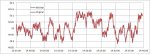
The printed output from the module was logged and fed into Excel.
If the mains frequency was exactly 50Hz, then 50 cycles should take exactly 1 second which would result in a timer count of 2^15 or 32768. If it was a bit less, the time period would be a bit longer resulting in a count that was greater than 32768. The formula in Excel for converting the period count to frequency is therefore 50*2^15/Timer Count.
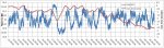
The Excel chart shows a frequency plot of our mains supply over a 5 hour period earlier today. I’ve also included a cumulative time error between the crystal and a count of the mains pulses. This suggests that the max error between the two during this period was about 3.5 seconds whereas our local standard sets an upper limit of 5 seconds. I say suggests because, the program only monitors the mains for 98% of the time (it misses a single pulse each second while it prints out the results) and the 32kHz crystal may not be perfectly accurate. Of course, it also assumes that the two times were in sync when I first started monitoring at about 3:15pm.