Speeding up some code

edmunds

Senior Member
Dear all,

Below is my line follower code. It is kind of working, but I believe it is too slow for actual operation even at the slowest speed of the car. Maybe I'm wrong. Or I hope I'm wrong :). The symptom is I can read the line with with the model car in my hand and I do get correct steering wheel movement. However, when I run the car at the slowest possible speed, it is able to perform one correction in the right direction to miss the line completely after that, because it does not seem to manage to do the counter correction after overshooting the line.

Now, I know it is a lot to ask for anybody to look at a complete piece of code that does not even fit into the limit of the post here, but if you have any ideas on how I could improve the calculation parts to make response to steering error quicker, I would be very thankful.

It is not impossible, that there is an electromechanical problem - the steering wheels are just not turning fast enough physically. I have not figured how to calculate or assess that at this point.

View attachment LineFollowerCarTest20161212.bas

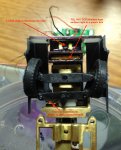
Just to give everyone a better idea of the physical setup, here is a picture of the underside of the front of the vehicle.

IMG_2039_Edit.jpg

Thank you for your input,

Edmunds
 
Last edited:

Circuit

Senior Member
Perhaps you may see a speed of execution increase if you replace your gosubs with macros. The program size will increase but given that you are using a 40X2 chip this should not be a problem. My understanding is that macros are compiled in-situ for each iteration within the program and therefore the speed of execution of calling a subroutine and then returning it is eliminated.

Alternatively, given that your mail loop is simply a call to four subroutines, why not write them directly into the main loop rather than calling them as subroutines. I understand that calling subroutines does slow things down slightly - especially as you are nesting subroutines as well. But if you want to keep the existing structure the simply replace the subroutines with macros.
 
Last edited:

Buzby

Senior Member
Hi edmunds,

If you say that the steering behaves correctly when the wheels are off the ground ( i.e when you are holding the car in your hand ), but fails with the car on the ground, that would seem to suggest a mechanical problem.

Have you tried programming the car to do some left-right turns etc. by just using code, without it trying to follow a line ?.

Your code is well structured, and there are a few tweaks you can make that will speed up the code, but I think that overall it should work as it is now with a very slow car.

Cheers,

EDIT : I just downloaded your code to a 28X2, and it looks like your code can execute about 20 scans per second, which should be fast enough for a slow car. I'm sure it can be speeded up, but I think either (1) there is a mechanical problem, or (2) there is an unseen problem in the algorithm.

Too late tonight for me to investigate further !.

Buzby
 
Last edited:

erco

Senior Member
edmunds: Can you upload a video showing the operation? Steppers consume a LOT of power and yet they can be very slow and/or miss steps. What voltage are you using for your stepper? You typically need higher voltage than they are rated for reliable operation. Can you use a servo for steering instead?
 

stan74

Senior Member
Is the sensor wider than the line? Then only a band of pixels are lit. You want the band in the middle so if the ones to the left of the band get lit then the car is going right so steer left and if the ones on the right get lit then the car is going left because they weren't lit before so go right.
Same if the line is wider than the sensor.If the left pixels become unlit then the cars going left off the line.
So just assume the pixels in the middle are on the line and just test the edges.
 

BESQUEUT

Senior Member
edmunds: Can you upload a video showing the operation? Steppers consume a LOT of power and yet they can be very slow and/or miss steps. What voltage are you using for your stepper? You typically need higher voltage than they are rated for reliable operation. Can you use a servo for steering instead?
+1

If speeding things is necessary, consider that storing data in scratchpad is of no-use !
leftedge is the first transition from a dark pixel to a white pixel
rightedge is the first transition from a white pixel to a dark one.

cal_expose is very time-consuming.
How many loop in the do loop ?

Considere calibrating exposure one time for N...

As used very often, SI_pulse: sould be a macro
 
Last edited:

BESQUEUT

Senior Member
EDIT : I just downloaded your code to a 28X2, and it looks like your code can execute about 20 scans per second, which should be fast enough for a slow car. I'm sure it can be speeded up, but I think either (1) there is a mechanical problem, or (2) there is an unseen problem in the algorithm.
How did you measure that without any hardware ?
 

Rick100

Senior Member
Hello Edmunds,

Like Buzby and erco , I think you have a mechanical or losing steps problem. You can run test code to cycle the stepper back and forth for a known number of steps, and see if it ends up where it started.

Good luck,
Rick
 

Buzby

Senior Member
How did you measure that without any hardware ?
I've got an AXE401.

Changed #picaxe to 28X2. Replaced readadc with a fixed value ( to prevent over/under exposure ). Put scope on C.1 ( the CLK ).

From this I can see the sensor is 'busy' for about 35mS, and not 'busy' for about 15mS, total cycle about 50mS, so the code is running at 20Hz.

Simples !
 

hippy

Ex-Staff (retired)
I haven't really studied the code, but if the code is SERTXD outputting "too light" or "too dark" messages at 9600 baud when not held that will slow the loop time down.
 

Buzby

Senior Member
I haven't really studied the code, but if the code is SERTXD outputting "too light" or "too dark" messages at 9600 baud when not held that will slow the loop time down.
I added a fix to replace readadc when I tested edmunds code, specifically to ensure that no bright/dark sertxd was active.

I also added two more to detect if left/right were active, as it could be that the left/right routines take too long to execute, so that by the time they finish the car is way off the line.
No left/right were active in my tests, so I've not been able to check the timing of these routines yet.

Regarding the use of sertxd to diagnose in real time, I agree it is too slow. I think it would be better to have a couple of LEDs to show bright/dark.
 

edmunds

Senior Member
Dear all,

Thank you for your responses. Sertxds are commented out and not used while testing 'on the road'. Trying to drive a, say, figure eight without any sensor inputs is a great idea that probably crossed my mind at some point, but I was now stuck in my own never ending loop with no branches available ;). I will do that when I get to the vehicle again, which might be this afternoon or tomorrow night.

@Buzby, special thanks for your measurements and further explanation on how you did them, I will have to try this out, too. It feels 20 updates per second should be plenty with good margin. I have not measured it, but my feeling from the actual operation is, there are a little more than one update per second. It is possible, this is due to Eline being small and for one reason or another it does not work. Exponential function instead of linear might help fixing this. I was just thinking even with linear algo only, I should get a zig-zag thing that at least tries to stick to the line.

I don't know if I can shoot a video without great effort, given how small this is and that is not really happy with a lot of light, but I will try.


Thank you all once again,

Edmunds
 

edmunds

Senior Member
So just assume the pixels in the middle are on the line and just test the edges.
Well, I was thinking about this at first, since I know the width of the line and I also know by now, how many pixels its reflection takes. But this would not work with lines of different widths, so I would prefer a solution, where I actually work with the centre of the line. But, thanks, this is a fair suggestion for making things faster with known width of the line.

Edmunds
 

edmunds

Senior Member
edmunds: Can you upload a video showing the operation? Steppers consume a LOT of power and yet they can be very slow and/or miss steps. What voltage are you using for your stepper? You typically need higher voltage than they are rated for reliable operation. Can you use a servo for steering instead?
Servo is not really an option unless the CD drive like stepper solution is a total failure. For very many reasons that would take this thread totally off topic. At the moment my stepper is running at 3.3V and it is rated at 3.0. So not a very good situation with that. Since I'm running of a single cell LiPo, I need a booster type power supply and I don't have any at hand of the size that I could really try. If motor operation turns out to be the problem, I will revisit the motor voltage among other things. Thank you for your suggestion.

Edmunds
 

edmunds

Senior Member
+1

If speeding things is necessary, consider that storing data in scratchpad is of no-use !
leftedge is the first transition from a dark pixel to a white pixel
rightedge is the first transition from a white pixel to a dark one.

cal_expose is very time-consuming.
How many loop in the do loop ?

Considere calibrating exposure one time for N...

As used very often, SI_pulse: sould be a macro
@Besquet,

These are all super suggestions, I will look into this. Thank you!
The number of loops could be the bottleneck by the way. If the figure eight test works, then this is the first place to start and I believe this is not reflected in @Buzby's test. If I can improve convergence, it could get a lot better. And at least for testing, I could calibrate, say once for 10 'follow_line' loops.

Edmunds
 

edmunds

Senior Member
Brr, back to square one with #macro - not supported on MacAxePad. I can compile on the schwindows thing, of course, but not immediately.

Edmunds
 

Buzby

Senior Member
Hi edmunds,

Before making significant changes to the code, I think we need to establish that the motor and mechanics are reliable, repeatable, and can be characterised.
There does seem to be an air of uncertainty here, and if it is so, you will chase yourself in circles writing more and more complex code.

Setting a few pre-programmed turns for checking and recording the behaviour is, I suggest, the first step.

Cheers,

Buzby
 

edmunds

Senior Member
Hi edmunds,

Before making significant changes to the code, I think we need to establish that the motor and mechanics are reliable, repeatable, and can be characterised.
There does seem to be an air of uncertainty here, and if it is so, you will chase yourself in circles writing more and more complex code.

Setting a few pre-programmed turns for checking and recording the behaviour is, I suggest, the first step.

Cheers,

Buzby
I'm on it as we speak :). Just realised this introduces the need to centre the wheels in one way or another. Tackling that at the moment.

Edmunds
 

BESQUEUT

Senior Member
Replaced readadc with a fixed value ( to prevent over/under exposure ). Put scope on C.1 ( the CLK ).
Is suppose that this value make Vout good.
Otherwise "Big calibration loop, exit only when Vout is good" is an infinite loop...
But in real world, how many loops before Vout is good ?
 

BESQUEUT

Senior Member
Brr, back to square one with #macro - not supported on MacAxePad. I can compile on the schwindows thing, of course, but not immediately.
This is not an issue...
Simply replace everywhere :
GOSUB Si_Pulse
by :
high SI: pulsout CLK, 10: low SI
(this is exactly what is doing a macro)
 

BESQUEUT

Senior Member
I'm on it as we speak :). Just realised this introduces the need to centre the wheels in one way or another. Tackling that at the moment.
Stepper is the hard way. A servo is many more usable for steering...
You need a reference point, either mechanical or optical.
Then, you need a counter to know how many steps from that point.
If you loose any step, at any time, your centre will fail...

Another way is to use a potentiometer... That is the way used by a servo...
 
Last edited:

edmunds

Senior Member
If you loose any step, at any time, your centre will fail...
I would argue this is not the case if my only goal is to stick to a line. Be it physical, like a white line on the road or calculated like a path for indoor navigation based on 6DOF sensor. I can always compensate for a missed step, because I know where I wanted to be compared to where I actually (or even imaginary) ended up. On top of that, steering is never precise. By design, there is some free movement, so you cannot go straight by just setting the wheels ideally straight. Also, for rear wheel drive with no differential and ackerman steering there is a lot going on beyond real possibility to calculate it. So, I imagine 'measure, adjust, compare to expected result and adjust more' is the way to go. This would be the same story with a servo. Given, servo has built in position feedback, but +/- 1mm error at the tip of the arm are about the best I have seen. For this size of the car that is about 25% of steering tie road travel range...


Thank you for your input,

Edmunds
 
Last edited:

edmunds

Senior Member
Here comes the video

It's not really an eight, did not want to do all the geometry now, but it is steering and it is not off by much on each iteration. It is consuming battery like crazy, though, but that is another topic/issue.

https://youtu.be/e_B4bjLgyy8

So, I will now try to figure out what happens with the calibration loop and how many times it is actually being executed before we consider ourselves calibrated.

Edmunds
 

edmunds

Senior Member
I now have something that is much better. I get two consecutive and increasing in amplitude zig-zags before the car wanders off in the unknown. I changed the code to calibrate only once on startup/reset and I'm getting noticeably more updates per second so the calibration procedure will have to be improved and limited in how often it is executed. The frequency of updates now seems like something that could work, if I could get it to compensate less for small deviations and more for large deviations. Also, the code does not handle situations, when the car can see a portion of the line, but implementation of that should be combined with making edge finding dynamic with no storing of data in scratchpad. All of this I think I know how to do or at least where to start, but have to call it a day. Hope to get some time for this tomorrow evening again.

Thanks everybody for great inputs,

Edmunds
 
Top