Setting up Datalogger

JPB33

Senior Member
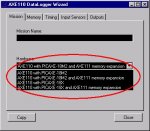
Trying to program the picaxe datalogger (alas bought at the old price!) from the wizard and get it to work. Read through the instructions in conjunction with the wizard but although I can set the info in the wizard (and RTC) then copy and paste it and then download it successfully to the logger no led's flash as per the instructions?

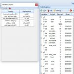
In case I was missing something passed it over to my good friend The Bear who reports similar results but gets variable clashes as a debug message, see pics, what am I doing wrong?

Thanks

24.11.16AXE110.jpg
 

hippy

Technical Support
Staff member
Will have to read the datasheet / think about for the LED issue but the Variable Clash is nothing to worry about.

The word variables are also defined as two separate byte variables (MSB and LSB) each with their own names. As this is an intentional clash you can ignore that.
 

Technical

Technical Support
Staff member
Note that the control register is reset to 0 at power up. So if you do not have the coin cell connected to maintain power, it will reset to the no-flash default. Remember the square wave LED pin is also an open collector style output.

Try writing the control register at the start of your own program


hi2csetup i2cmaster, %11010000, i2cslow, i2cbyte
hi2cout 7, ($10)
 

JPB33

Senior Member
Thanks for the replies. Afraid I'm really out of my depth on this one at present, sorry!

Tried the suggestion about the control register witout effect. The TRTC battery is inserted and is reading 3.2v so looks ok.

Downloaded a 50 readings at 1 sec interval program using pause instead of the RTC and a red LED appeared after a few minutes which is the end of the run? Thought this should be 50 secs?

After downloading what LED should light up? Tried taking various inputs high, according to the info an LED should light but nothing?

Is there a test program I can try anywhere?

Thanks
 

Technical

Technical Support
Staff member
Is there a test program I can try anywhere?
The wizard creates a fully commented program. You really need to take the time to read through it and digest it to understand how to use the system.

The delay will be number of readings x time interval selected (+ processing time of each loop). The LED action will be there if you activate the 'bicolor' LED option on the final tab of the wizard. The comments in the generated program describe how the LED works. e.g.

Code:
[COLOR=Black]read_sensors:
        [/COLOR][COLOR=Blue]high B.3                           [/COLOR][COLOR=Green]; flash green LED


        [/COLOR][COLOR=Blue]readadc C.0[/COLOR][COLOR=Black], [/COLOR][COLOR=Purple]data0                 [/COLOR][COLOR=Green]; read Light
        [/COLOR][COLOR=Blue]readtemp C.7[/COLOR][COLOR=Black], [/COLOR][COLOR=Purple]data7                [/COLOR][COLOR=Green]; read Temperature


        [/COLOR][COLOR=Blue]low B.3                            [/COLOR][COLOR=Green]; end of green LED flash
        [/COLOR][COLOR=Blue]return[/COLOR]
If it doubt just write a test program to flash B.3 on and off - does the LED flash?

The RTC will only work if you have first set the time using the RTC wizard.
 

JPB33

Senior Member
Discovered if I use PE5 I can program a new mission and it will autorun, flash green when aquiring then red at the end, I can also retreive and display the data. That is using pause instead of the RTC.

Cannot get the RTC to program or achieve the same results with PE6. Should it work in PE6?

Thanks
 

hippy

Technical Support
Staff member
Cannot get the RTC to program or achieve the same results with PE6. Should it work in PE6?
<joke>
No; we decided to annoy users by deliberately making it not work.
</joke>

If you can post the details of how you are configuring the mission in PE5 we can compare the results with PE6 and will investigate to see what the issue is.
 

JPB33

Senior Member
Getting my head round it all a bit more after keep re-reading the posts from technical and hippy---Thanks for your pateince and help

Checked the voltages on the RTC ic but they seem fine as does the backup battery voltage and on the ic pin but cannot program it so perhaps the DS1307 is dead?

Program a mission for 50, 1 sec readings with pause as timing and both PE5 & 6 produce a result which looks like the right time on the graphs but PE6 doesnt flash the LED green as its taking the reading, PE5 does, PE6 only goes red at the end.

Following technicals suggestion successfully downloaded this test program to the board but the led doesnt do anything?


do
pause 1000
high B.3
pause 1000
low B.3
loop
 

hippy

Technical Support
Staff member
Checked the voltages on the RTC ic but they seem fine as does the backup battery voltage and on the ic pin but cannot program it so perhaps the DS1307 is dead?
Possibly. You could download a test program to check the functionality of the DS1307. What voltages are you reading ?

Program a mission for 50, 1 sec readings with pause as timing and both PE5 & 6 produce a result which looks like the right time on the graphs but PE6 doesnt flash the LED green as its taking the reading, PE5 does, PE6 only goes red at the end.
So, apart from the DS1307 problem, is the only "it doesn't work" issue with PE6 that the green LED is not flashing for each reading ?

If your DO-LOOP test code for toggling B.3 and its LED does not work that suggests there is some hardware issue with the board, that the LED on B.3 cannot be controlled. I am not sure why that would be if B.3 can control the LED when done as part of a mission programmed via PE5.

I am not familiar with the Datalogger, still haven't yet looked at its datasheet, but the PE6 mission wizard describes it as a bi-colour LED on B.2 and B.3 so it may require both pins to be outputs. I would try -

Code:
Do
  Low  B.2 : Low  B.3 : Pause 1000
  Low  B.2 : High B.3 : Pause 1000
  High B.2 : Low  B.3 : Pause 1000
  High B.2 : High B.3 : Pause 1000
Loop
That should light both red and green LED's.

It could simply be that the PE6 mission isn't setting both pins to light the LED. It may have inadvertently been coded to use two separate LEDs and only alter one pin without having set the other. We will have to check that.
 

hippy

Technical Support
Staff member
It could simply be that the PE6 mission isn't setting both pins to light the LED. It may have inadvertently been coded to use two separate LEDs and only alter one pin without having set the other.
At first glance it looked like that might have been the problem but it doesn't appear it is the case. The first thing the mission does is "dirsB=$FF" which should set all B.x pins as output low. Then setting B.3 high should light the green LED.

It will be interesting to see what the result of running the code in post #11 is.

What I did notice is, if a temperature sample is not taken in the mission, for both PE5 and PE6 wizards, the time the LED is flashed for is extremely short, there is just a READADC between the HIGH and LOW, so maybe the flash is just too short to be seen ?

Perhaps temperature is not being sampled in your PE6 mission but is in the PE5 mission ?
 

JPB33

Senior Member
Now got the DS 1307 problem sorted, re read the circuit and did more voltage measurements around the ic and realised that there was nothing on Pin 7, more digging and the green LED was the wrong way round. Swapped it around and now its happily flashing at 1hz after being set via the wizard The RTC can be used to time the mission with sample LED flashing in PE5 but Not 6, goes red at the end of the mission with both simulators.

Downloaded and ran the code from post #11 and the LED flashes red and green. Programmed missions with various inputs omitted but no difference to the sample led.

I want to monitor the state of 4 outputs from a 20M2. Does anyone know if I can modify the temp and light sensor inputs for general purpose use by removing the relevant resistor or does the software need modifying as well?

Pleased with the progress, great to see the RTC LED flashing at 1Hz!

Thanks for the help.
 

JPB33

Senior Member
Tried posting the code of a 50 reading mission at 1 sec intervals in PE5 and PE6 for comparison as requested but unable to do this as get an error message saying it too long at 11351 characters?


Is there a way round this?
 

hippy

Technical Support
Staff member
You should be able to include a file of that size as an attachment, and if it were a lot larger could put it in a ZIP file and post that as an attachment.

Use Reply then "Go Advanced" button to get to the file attachment manager.
 

JPB33

Senior Member
Ok, thanks as ever Hippy, fingers crossed, here goes.


As requested attached is a 50 reading mission at 1 sec intervals in PE5 and PE6, both run until the red LED at the end, however PE5 flashes as its taking readings PE6 doesnt. Notice that PE6 line 4 refers to an 18X which I need to comment out before the program can be downloaded, also tried inserting a delay into read_sensors section without any effect.

Does the green input LEd flash for other datalogger users when its taking readings from the PE6 download?

What have I got wrong?

Thanks
 

Attachments

hippy

Technical Support
Staff member
Notice that PE6 line 4 refers to an 18X which I need to comment out before the program can be downloaded
That might be the problem. If you are using code generated for an 18X but running it on an 18M2 it will not be configuring the 18M2 I/O pins to be how the 18X pins would be.

That would tie in with my comment in post #12; "The first thing the mission does is "dirsB=$FF" which should set all B.x pins as output low". That's only true when generating code for an 18M2 mission; that command is not present when generating an 18X mission.

Without that command, on an 18M2, port B will remain as input so, while "HIGH 3" (B.3) should flash the green LED, it doesn't because pin 2 (B.2), the other end of the bi-directional LED, is an input. On the 18X the B.2 pin will be an output low so does flash.
 

Attachments

Last edited:

JPB33

Senior Member
Yes that was it, completely missed! Couldnt get my head round your comment in #12 it but obvious now. LED now bravely flickering away.

Thanks once again Hippy---another mystery solved---cheques in the post...
 
Top