lbenson
Senior Member
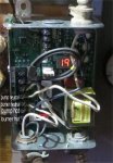
I want to monitor on/off on my 120V boiler and shallow well water pump. The boiler aquastat has accessible AC lines for the pump and the burner (individual wires for hot and neutral). The boiler circulating pump is 1/6th horsepower, and the burner is of unknown amperage, but I have read online that it might be as much as 7-8 amps.
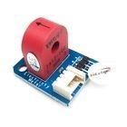
I have tested one of these "up to 5 amps" current sensors with 13W CFL and 60W incandescent bulbs, and a picaxe easily detects on/off using ADC. I summed ADC readings for a second, and over a given threshhold (determined experimentally), the light was on.
http://www.ebay.com/itm/162136721044
The circulating pump should be under 5 amps (but I don't know about stalled), but the burner looks to be able to surpass that. I have not done any experimenting yet, and am away from the equipment. What would happen to that sensor (and the picaxe) if the current exceeded 5 amps?
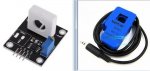
I also have this sensor, rated for 30 amps. The problem with it is that it is too large to fit in the aquastat box. I wish to be as non-invasive as possible. I can probably use this sensor in the large switch box of the shallow well pump. I can enclose the smaller sensor in its own plastic box with the mains neutral fed through the box and through the sensor.
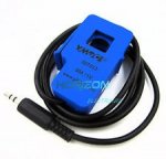
http://www.ebay.com/itm/SCT-013-030-Non-invasive-AC-Current-Sensor-Clamp-Sensor-30A-Good-/281687168935
I'm not trying to measure the current, just whether the pump/burner is on or off. Is there an easier safe way of doing this?
In a related matter, I understand that low-voltage wiring in a box which contains mains voltage must be fire rated. Where is such wiring found and how is it designated in the U.S?
I have tested one of these "up to 5 amps" current sensors with 13W CFL and 60W incandescent bulbs, and a picaxe easily detects on/off using ADC. I summed ADC readings for a second, and over a given threshhold (determined experimentally), the light was on.
http://www.ebay.com/itm/162136721044
The circulating pump should be under 5 amps (but I don't know about stalled), but the burner looks to be able to surpass that. I have not done any experimenting yet, and am away from the equipment. What would happen to that sensor (and the picaxe) if the current exceeded 5 amps?
I also have this sensor, rated for 30 amps. The problem with it is that it is too large to fit in the aquastat box. I wish to be as non-invasive as possible. I can probably use this sensor in the large switch box of the shallow well pump. I can enclose the smaller sensor in its own plastic box with the mains neutral fed through the box and through the sensor.
http://www.ebay.com/itm/SCT-013-030-Non-invasive-AC-Current-Sensor-Clamp-Sensor-30A-Good-/281687168935
I'm not trying to measure the current, just whether the pump/burner is on or off. Is there an easier safe way of doing this?
In a related matter, I understand that low-voltage wiring in a box which contains mains voltage must be fire rated. Where is such wiring found and how is it designated in the U.S?