Radio control to DC conversion

Videostar

New Member
Hi

I'm trying to convert the output of a radio control receiver which has variable pulses (from 1ms=0 to 2ms=1 every 20ms) to give me a variable DC voltage output that is fairly linear. I can cope with a variable PWM output if I have to but would rather have a smooth variable voltage. I actually want 0-24V but I can level shift any output with an OpAmp. I have a fair number of 18M2+ and some project PCBs (both types) from a previous project and was hoping to utilise them if possible.

Any ideas about how I go about achieving this ?
 

hippy

Technical Support
Staff member
At 4MHz, a PULSIN will read a pulse length of 100 for a 1ms pulse, 200 for a 2ms pulse. You can convert that to a 0% to 100% range of PWM duty from 0 to 1023, and then RC convert that to a voltage. Something like -

Code:
PwmOut ... , 255, 0
Do
  PulsIn ... , ... , w0
  w1 = w0 Min 100 - 100 Max 100 * 511 / 50
  PwmDuty ... , w1
Loop
 

Videostar

New Member
Many thanks hippy,

Is that really all there is to the code (apart from the pin constants etc.) ? I can't believe how simple it is.
I assume that I am able to use the 18M2+ even though I know it is "overkill".
 

eggdweather

Senior Member

hippy

Technical Support
Staff member
Is that really all there is to the code (apart from the pin constants etc.) ?
Should be and should work on the 18M2+.

There are some tweaks which could be had; running the PICAXE faster which will give you greater resolution of the inputs, eg at 4MHz you have 100 steps between 1ms and 2ms, at 16MHz that increases to 400 steps. That should make voltage changes smoother.

The only thing other than adding pin numbers is polarity of the pulse and even that can be determined by the code. It is easy to tell if a pulse is less than say 10ms ( 1000 reading at 4MHz ), if so that's the 1ms-2ms pulse, otherwise it is the 18ms-19ms gap between pulses. Untested but should work ...

Code:
#Picaxe 18M2

Symbol RXD_PIN = ?.?
Symbol PWM_PIN = ?.?

PwmOut PWM_PIN, 255, 0
PulsIn RXD_PIN, 0, w0
w2 = w0 / 1000 Max 1
SetFreq M16
Do
  PulsIn RXD_PIN, w2, w0
  w1 = w0 Min 400 - 400 Max 400 * 63 / 25
  PwmDuty PWM_PIN, w1
Loop
That "w2 = w0 / 1000 Max 1" may not be immediately obvious; if the measured low period is greater than 10mS then the pulse to use must be a high (w2=1) else a low (w2=0).
 

Videostar

New Member
Thanks erco, that PCB would be ideal if the output was omnidirectional (I need to replace a 10k pot which is across +24V to ground with the slider feeding a variable voltage).

hippy, many thanks for the tweeks. I will attempt to try it in the next few days if I can manage to get interruption free.
 

Haku

Senior Member
Videostar, just curious, what are you controlling via RC that needs 0-24v?

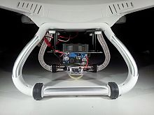
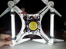
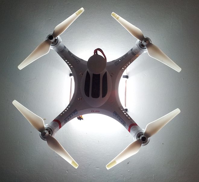
I recently made an RC switch using an 08m2 so I could turn on/off a 50 watt LED attached to the bottom of one of my quadcopters:


When it's up in the air holding position through GPS it produces a big round circle of light on the ground, enough to clearly see anyone/anything in the area. I tried to take some video but none of my sportcams are any good at night.
 

Videostar

New Member
Thanks hippy

The code appears to work although the output doesn't reach zero or full output. I suspect that may be the settings in the transmitter which I will investigate next.
 

Videostar

New Member
Hi Haku

I'm trying to remote control an analogue power supply. It's variable control (10k) is connected between +24V and 0V. If I can supply a 0-24V output from the 18M2 project PCB to where the slider should be connected I can remote control it - I'm just being idle, I don't want to have to keep walking to the far end of the workbench to change the voltage (sad, I know).
 

Videostar

New Member
Hi stan74

That was how I was planning to convert the PWM to linear but using discrete components on the project PCB rather than an extra PCB.
 
Top