08M2 controlling 12v DC motor via L293D - Help!

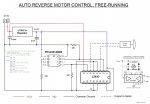
Hi, I have built the attached circuit but can't get it to work. If I place a high (5v) on pins 5 OR 7 (C0 or C2) (with the 08M2 removed) then the motor will turn in either direction as designed. But the 08M2 does not seem to be able to drive it. All I get is a slight twitch at each 20 second interval as if it's trying which appears to prove the code is at least running. Any ideas?
 

Attachments

Jeremy Harris

Senior Member
There doesn't look to be anywhere near enough supply decoupling, so I suspect that motor noise, or a supply brownout as the motor turns on, may be causing the Picaxe to reset.

The Picaxe chip needs a 0.1µF across the supply, as close to the pins on the chip as you can get. You also need a reservoir capacitor and perhaps some high frequency decoupling across the 12V supply, as close to the L293D as possible. I suggest adding a 100µF electrolytic across the 12V rail, with a 0.1µF in parallel with it, to try and remove the motor noise.
 

Circuit

Senior Member
Your inset diagram from the datasheet shows Vcc1 and Vcc2; two separate supplies. It is worth trying this out; provide a second power source for the motor to separate it from the power source to the PICAXE. As Jeremy indicates, there appears to be too direct a link between the motor and the PICAXE power supply; upon starting the motor may drop the supply voltage sufficiently to reset the PICAXE. A 100uF electrolytic across the PICAXE power pins may help the situation. Overall, I would suggest two voltage regulators; one feeding the motor and one feeding the PICAXE and with 100uF electrolytic caps on the supply line to each regulator. A lot will depend upon just how "dirty" your motor is - a higher amp motor will be much more aggressive in placing noise on the line than a small "solar" motor. PICs work best with a really clean power supply. You can also suppress the motor; start with putting 470nF across the supply leads. From your other threads I think you are familiar with model railways; look at the suppressors that are placed on locomotive motors and that will give you some idea of what is involved. The preferred method is usually ceramic caps between the brushes and from each brush to the metal case of the motor.
 

hippy

Technical Support
Staff member
As the twitch is every 20 seconds, the length of the wait from starting before switching the motor on, it seems likely to be the PICAXE resetting, through interference or a collapsing power supply.
 
Looks like I fixed it guys! After all the additional caps and everything it started doing strange things like when I put an input to the driver and it kept on running after I took it off! So decided to go back to basics and removed all the caps etc and still doing it, then I found a blob of solder across 2 tracks and that got rid of that problem so back to square one. In the mean time a thought bubble popped out of my head saying "try a different (type of) motor". So I did and the b****y thing worked!!

I was thinking about the post from CIRCUIT above, and locos with their interference caps across the brushes, and remembered I kept some of those caps when I converted some old locos to DCC which don't need them. This motor is a sealed can type so can't get to the brushes but I just stuck one across the output terminals and EUREKA! Low and behold it fixed the problem. It has been chuntering back and forward now for half hour or so so I'm well chuffed - that's 2 problems fixed in 2 days. I do have a third problem but I'll leave that to another day, I'm sure you are fed up with seeing my monica on here all the time!

Many thanks for all your very helpful replies, especially from CIRCUIT who set me off in the right direction. It certainly has been educational.
 
Top