rfout/rfin

friis

Senior Member
Hi,
I have a setup with 2 Picaxe 14M2 and 2 Gorji TX and RX with the following pgms:

#Picaxe 14M2
#Terminal 4800

MAIN:
high b.3
pause 2000
low b.3
pause 100
rfout b.5, ("aaaaaaaa")
sertxd ("aaaaaaaa",cr,lf)
pause 2000
goto MAIN

#Picaxe 14M2
#Terminal 4800

MAIN:
high b.3
pause 500
low b.3
sertxd ("START",cr,lf)
low c.1 ;enable the receiver
pause 100
rfin c.0, b1,b2,b3,b4,b5,b6,b7,b8
high c.1
sertxd (b1,b2,b3,b4,b5,b6,b7,b8,cr,lf)
goto MAIN

which dont work.

Sometimes the receiving pgm receives 8 bytes, but they are garbled - most of the time the receiving pgm receives nothing.
I have had the pgms work with serout/serin.
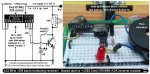
A scope shows that the transmitter transmits and it looks regular as "aaaaaaaa" should. The scope also shows that the receiver is enabled and appears to receive data (but that is normal for the Gorji receiver), but the rfin statement does not get executed.
Can anybody help?

The 17/3-12 Goytex wrote that he had tried the Doji with rfout and rfin - and it worked. But how?

best regards
torben
 

hippy

Ex-Staff (retired)
The 17/3-12 Goytex wrote that he had tried the Doji with rfout and rfin - and it worked. But how?
Not sure; do you have a better link to that ?

I am not familiar with Dorji modules; which particular modules do you have ? And do you have a link to their datasheets ?

What you have would appear to be right so it may be a hardware issue. If the receiver module is receiving data but RFIN is not it might be a voltage issue. How do you know the receiver is receiving data ?
 

BESQUEUT

Senior Member
I think that you have to remove the pause 100 command

As soon as C.1 is low, data can be send.
So you have to read data as soon as possible.
If the emiter needs some delay, rfin will wait as it is a blocking command.

When received, what are the "garbled" data ?
 

friis

Senior Member
Hi hippy and BESQUEUT,
Here is the link to Goytex:

http://www.picaxeforum.co.uk/showthread.php?20825-Interesting-new-433-MHz-ASK-
modules&highlight=rfin+dra886rx

Here is the link to the data sheets for Dorji dra88Xrs and Dorji dra887tx:

http://ex.kabobo.ru/tw_files2/urls_26/40/d-39607/7z-docs/2.pdf

I know that the transmitting module does transmit because the sertdx statement
in that module produces the list:

.
.
.
aaaaaaaa
aaaaaaaa
aaaaaaaa
aaaaaaaa
.
.
.

I know that the receiver is receiving data (from where?) because the sertdx
statement in the receiving module produces the list:

.
.
.
START
*[9A]=e[9E][C6][E3][03]
START
[B9]6[12]9[[90][CE]V
START
[8D][BF][FF][C9][A5][AA]/[F4]
START
[BB]9[D9][F7]3o[CA]x
START
[04][0E][AB]'[DF][B8][BD]q
START
[B1]E[93][D2]OP[F7]0
START
W[9B][F3][BF][BB][92][EC][01]
START
[16][DA][85]Ie[82]r[A9]
START
[CB]+[E5][EF][81][BC] [F1]
START
aaa[02][14],,m ***************************************
START
[85][DF][AD]2P[BB][EF][0C]
START
B[C1][16][E8][A4][CA][92][A7]
START

The line marked with ***************** actually contains aaa which is part of
the data sent (aaaaaaaa). But data are mostly garbled and there is a lengthy
pause between receptions.

Removing the pause 100 had no effect.

I am using 5V, which is what the Dorji module need.
torben
 

hippy

Ex-Staff (retired)
I would suggest permanently powering and enabling transmitter and receiver, removing all the superfluous code from the program -

Code:
#Picaxe 14M2
#Terminal 4800
Do
  Pause 2000
  RfOut B.5, ( "aaaaaaaa ")
  SerTxd( "Sent " )
Loop
Code:
#Picaxe 14M2
#Terminal 4800
Do
  RfIn C.0, b1,b2,b3,b4,b5,b6,b7,b8
  SerTxd ( b1,b2,b3,b4,b5,b6,b7,b8, CR, LF )
Loop
 

hippy

Ex-Staff (retired)
Unfortunately this is like trying to determine why a letter posted never got to its intended recipient. We know it did not arrive but we do not know why not. That is going to require investigation.

Best place to start is in detailing exactly how you have things set up, posting full circuit diagrams and photos.

Did you check the voltage out of the receiver module ? Are you able to take a screen shot of the scope showing the output or detail the timing ?
 

Goeytex

Senior Member
I do not have any M2 chips to setup/test at this time. However, the attached diagram shows how I recall setting up the hardware. I do not recommend powering the TX module via an I/0 Pin. Use a transistor as shown to assure full voltage/current to the module. Make sure the RF and TX modules are separated by at least 1 meter to avoid swamping the receiver.

Do not omit the 10uf capacitors. They serve as bulk storage for the RF modules. Place them close to the module Vcc Pin.

Try operating the Picaxe Chips at 8MHz or 16MHz and see what happens.( 4MHZ and 4800 baud is not a very good combination on a Picaxe). You will need to adjust the terminal baud rate when changing Picaxe Clock speed.

Simply the code as in hippy's example.

If not solved, post your schematics and clear photos of your board/setup.

Goey
 

Attachments

friis

Senior Member
Hi Goeytex,

I will go and get the 10uF capacitors and the 2N3904 transistor.

In the meantime I quote from the Picaxe manual/rfout:

Effect of increased clock speed:
This command only functions at 4MHz. M2 and X2 parts automatically use the
internal 4MHz resonator for this command.

So I cant change the frequency?

I tried your transmitter diagram with the pgm:

#Picaxe 14M2
#Terminal 4800

MAIN:
high C.0
do
high b.3
pause 2000
low b.3
rfout b.5, ("aaaaaaaa")
sertxd ("Sent",cr,lf)
loop

without the 10uF, with the C.0 = TX_PWR (the transmitter permanently powered)
and the transistor = 2N2221A. It seems from the scope and the Serial Terminal to
be sending alright. But we will see with 10 uF and 2N3904.

I will send photos to you and hippy.

torben
 

hippy

Ex-Staff (retired)
I will go and get the 10uF capacitors and the 2N3904 transistor.
No need for that, and best not to. Keep everything permanently powered to start with, take power connections direct to power rails. Otherwise it adds in the possibility that it may be turning power on and off which is causing the problems.

Get things working when permanently powered. Once that's working then move to switched power.

Effect of increased clock speed:
This command only functions at 4MHz. M2 and X2 parts automatically use the
internal 4MHz resonator for this command.

So I cant change the frequency?
You can choose any frequency you want, but when RFOUT or RFIN commands are executed the PICAXE will drop to 4MHz while they complete. The PICAXE will return to whatever frequency had previously been selected after they have completed.

It seems from the scope and the Serial Terminal to be sending alright.
Unfortunately, only by looking at the RF the transmitter puts out, can it be said that sending is working. The scope and Terminal output will show the transmitter should be working, is being given the correct data, but that does not mean it is transmitting correctly.

There could be a problem at any place marked in the diagram below, and there may be multiple problems. This is what can make debugging RF set-ups which do not work so difficult -

Code:
                     \|/ ... \|/
.--------.    .----.  |       |   .----.    .--------.
| PICAXE |--->| TX |--'       `-->| RX |--->| PICAXE |
`--------'    `----'              `----'    `--------'
     |     |     |    |   |   |     |    |      |
 

Goeytex

Senior Member
There is no need to change the transistor from 2N2222 to 2N3904. Both are general purpose and will work equally well.

But do as hippy advises in regards to the transistor.

Do not use the transistor when troubleshooting the RF link. Keep the TX and RX permanently powered/enabled. That means direct power to the TX and direct grounding of the EN pin on the RX. When troubleshooting, eliminate anything that is not necessary for the RF link. That includes sensors, or any other device attached to the Picaxe or to the breadboard that is not necessary for the RX and TX to communicate.

However, I do recommend using at least a 1uf capacitor across the power connectors on both the RX and TX modules. In my finished projects, I use both a 100nF and 10uF , where the 10nF acts as a local bypass and the 10uf acts as bulk storage.

You have not mentioned your power source. Noisy or inadequate power supplies can significantly affect RF performance. Make sure your power supplies are clean. If possible use batteries for troubleshooting. If already using batteries make sure they are at full capacity.

If there is florescent lamp or other source of radiated electrical noise near where you are testing ... turn it off.

Goey
 

friis

Senior Member
Hi hippy,
That is right - I dont know if the transmitter is actually sending something
from the scope and the Serial Terminal. But the receiver is receiving something
sometimes and that must come from the transmitter. Can't be noise (I think).

I have alraedy tried the permanent power - as a matter of fact, that is also
what I am doing with Goeytex' design - viz. the pgms above.


I have implemented Goeytex' design as shown in the attached photos, but the
result is the same.

Actually, I have trouble attaching the photos, so I will send them separately.
torben
 

Attachments

hippy

Ex-Staff (retired)
But the receiver is receiving something sometimes and that must come from the transmitter. Can't be noise (I think).
I would suggest it quite possibly is noise or interference. From other posts it appears that Dorgi devices may be quite sensitive and therefore more prone to outputting noise than other manufacturer's devices.

The algorithm for RFIN is quite robust, is based on what is included in the NKM2401 Manchester Deecoder. It is quite surprising that so much 'random data' is getting through that algorithm which could suggest a high amount of noise, interference or corruption of the signal which is seen.

Perhaps also try with different manufacturer's transmitter and receiver modules, or compare to results using an NKM2401-based receiver.

It may be worth trying SEROUT and SERIN transmission of data through the modules to see if they work any more reliably than RFOUT and RFIN. That should be achievable without changing the hardware you have.

I cannot recall if RFOUT can be fed direct to RFIN on another PICAXE. It may be worth trying that with both PICAXE 0V's connected and 1K inline on the signal line.

By determining what does and does not work it may be possible to determine what the issue may most likely be.
 

manuka

Senior Member
Friis: Your pix implies a rural location that "should" be low on UHF interference. Best you clarify however, as UHF band noise can very devious. For all we know there may be the likes of a NATO spy base nearby...

If you've no UHF monitoring gear perhaps rustle up a 433 MHz sniffer- see attached. These are extremely handy when clarifying problems such as yours!

FWIW the 433 MHz game has moved on to such smart combo TX/RX modules as the US$5 HC-12- pictured. These have been extensively applauded/discussed on this forum & also the wider wireless data community. Google ! Stan.
 

Attachments

Last edited:

neiltechspec

Senior Member
I'd agree with the HC-12 mentioned above.

I'm in a densely populated area with all sorts of UHF crap filling the airwaves,
30 metres very reliabley achieved with 12mw @ 434.6Mhz from two DIY Wireless PIR's
with the supplied simple helical antennas on the TX's and 1/4 Whip on RX.
Not missed a single 60 second handshake for months, using simple serout/serin commands.

Neil.
 

friis

Senior Member
Hi everybody,
The situation is this:
1. I have a setup with 100nF and 10uF and the transmitter permanently powered
and the receiver permanently enabled as recommended by hippy and Goeytex. I have
batteri power on both transmitter and receiver.
2. The system works with RFIN/RFOUT and wires connecting transmitter and
receiver. That means that the software and 14M2 modules work with RFIN/RFOUT.
3. The system works if RFIN/RFOUT are replaced by SERIN/SEROUT. So the
transmitter and the receiver are also OK
4. With RFIN/RFOUT without wires I occasionally receive a transmission of 8
bytes, but it is garbled
5. Some of the transmissios that I do get start with aaa or aaaa which are
the first caracters of what I sent.
6. The system I was going to us RFIN/RFOUT on is now running using
SERIN/SEROUT. There are a few erroneous transmissions but they are rather far
between. I dont think that my environment is especially noisy.

I have searched the net extensively and I find quite a few questions like "have
you used PICAXE with Dorji modules" and some answers that indicate that "they"
have done that, but nothing clear.

I have found in the PICAXE manual the following:

This circuit only
supports transmitters that require under
20mA current, for higher power units use a
transistor switching circuit to power the
transmitter instead.

I think that the PICAXE transmitter needs more than 20 mA, but I dont
understand what a "transistor switching circuit" is - unless it is what Goeytex
proposed.

torben
 

PhilHornby

Senior Member
I initially looked at RFIN/RFOUT for a project, but was extremely disappointed by the results. Since I had an urgent need to get something working, I abandoned that approach and went Bluetooth. That came with its own issues and I eventually replaced HC-05 Bluetooth with HC-12 UHF modules, which are cheap and very easy to use.

Unless you have a requirement to communicate with an existing device that talks 433MHz ASK, my advice is: "don't" :(

I think the issue with RFIN, is that it is easily tricked by the IMMENSE amount of noise that the 433MHz ASK receivers generate. There is so much noise, that the single byte checksum succeeds randomly, and it spits out 8 bytes of nonsense, thinking they are real data.

I looked at RFOUT in some detail: It sends a byte of (Manchester-encoded) zeroes (presumably to help 'train' the receiver) and a byte containing "9". This byte is presumably a count of the total no. of bytes. Data is sent MSB first. Your 8 data bytes follow, then a single byte Checksum. I found this described as a CRC, in this datasheet, but for the single data-set I examined it was definitely just a checksum of the "9" and the 8 data bytes.

I think RFIN/RFOUT are only usable, if you implement some sort of handshake, to signal that real data is being sent. Perhaps send a 30mS "ON"/"OFF" blast of RF and only issue RFIN when you have detected that.

Regards switching the 433MHz transmitter - I have several projects that just feed VCC on the transmitter, from a pin on a Picaxe. I added a 10uF cap. because I could see my data modulated on top of this supply :eek: Probably not the way to do things, but nothing melted :) I recently came across a webpage, that pointed out that the 433Mhz transmitters tend to draw no power anyway, unless the DATA is low (because that pin goes to the emitter of a transistor on the module) ... in other words, you can just leave them powered all the time. I've not got round to testing this theory.
 

manuka

Senior Member
PhilHornby: Your RFIN/RFOUT thoughts echo my own.

Friis:Check a simple transistor switching circuit in my 2012 era DORJI .pdf

Both Inverted "N" coding (hence N2400) idles low and the transmitter indeed will be off if not data sending.

Remote NZ may seem less prone to UHF noise,but I live across the 10km wide harbour from our capital (Wellington) & a veritable dawn chorus of city sourced chirps,whistles,rasps & buzzes flood the local 433 MHz spectrum. Most of my past Dorji module ASK work however successfully used directly driven 08Ms & SERIN/SEROUT to good effect. I've never used/needed the likes of 10uF caps. - almost all my PICAXE circuitry is battery powered.

EXTRA: Although I knew of Dorji's smaller 2014 era DRA887RX,they now seem to have totally discontinued their 6 pin DRA886RX ASK receiver in favour of this 4 pinner. I've done nothing with the DRA887RX- anyone ? Stan.
 

Attachments

Last edited:

Goeytex

Senior Member
Looking back at my old notes, I may have used a DRA887TX Module when testing RFIN/RFOUT. This module outputs a whopping 17dBm @ 5V compared to the paltry 5dBm of the DRA886TX. I also put both modules on breakout boards with coax connectors and 1/4 wavelength antennas. Thus my decent performance.

The Dorji DRA886TX has an output of 5dBm at nominal 5V Supply. This will be reduced with a battery supply of 4.5V and reduced even further if the batteries are not at full capacity.

What this means that you could probably throw a paper airplane further than the range you will get with this module unless conditions are ideal.

Ideal Conditions:

1, 5.0V Power Supply (low ripple)
2, 172.8 mm Antenna on both RX and TX (6.8 inch)
3, 2400 or lower baud rate
4, No obstructions between TX and RX (Line of sight)

@Fris,

So far you have not told us the distance between the RX and TX modules, what obstructions there might be, measured battery voltage, or antenna length. We have not yet seen a photo of your setup.

My suggestion at this point is to abandon RFOUT/RFIN and setup using Serout/Serin. For good range use 2400 baud (N2400_16). For better range use 1200 baud (N1200_8). Use proven code that is posted in these forums. (Preamble, syncword, data bytes).

As has been noted, Dorji no longer sells the DRA886RX/TX modules and now has upgraded ASK RX and TX modules. Check your local regulations but I think that 13dBm is the max legal TX output there,( it may be 10dBm). So you may want to consider upgrading to DRA887RX and DRA885TX (10dBm @ 3.0V). You could operate the the DRA885TX and associated 14M2 @ 3.3V and probably be legal. The RX side needs to operate at no less than 3.6V so 3 AAA batteries will work fine.

Alternatively you may want to consider upgrading to smart RF transceiver modules that include a processor with UART. I see some TI CC1101 base modules (HC-11), and Si4463 based modules (HC-12) that are not too expensive but will perform several orders of magnitude better than any dumb ASK module.
 

manuka

Senior Member
-but will perform several orders of magnitude better than any dumb ASK module
Ah- perhaps take that as antipodean hype! I've recently given HC-12 modules an extensive workout & typically manage ranges of a few hundred metres under surburban clutter (light vegetation & timber buildings etc), with semi LoS approx. a km.

At 433 MHz & 10/25mW TX power only you'd need the likes of LoRa™ to extend ranges by "orders of magnitude".
 

Attachments

Goeytex

Senior Member
Ah- but I said "perform" which is not just range alone ... one order of magnitude for ease of setup, one for reliability and one for range. (Is that "several"?)

What I have found the dumb ASK modules perform very well at ... is jamming the neighbors auto alarm systems. Got up one morning at about 6:30 AM, went outside and casually noticed that several neighbors along my street had the hoods up on their automobiles, tinkering about,. Thought nothing of it until after a cup of coffee and I went into the lab and noticed a powered up breadboard. I had accidentally ( and carelessly) left a test running on one of those 17dBm Dorji TX modules. It was repeatedly sending a "QQQQ" preamble every 20ms at full power (100mw).
 

friis

Senior Member
Hi everybody,
I agree with PhilHornby - the receiver puts out so much noise that the
transmission cant get through properly. Sometimes something garbled gets
through, sometimes even with some of the transmission intact. That fits the
picture.

I have tried with distances between the TX and RX of 1m, 2m and 10M with some
gypsum walls between and got the same result.

So I will abandon my present experiments with RFOUT/RFIN and stay with my
system with SEROUT/SERIN. That works fine through all of my inner and
outer house walls and into the garden, but I dont know the actual range. I have
5 V, 172,8 mm antennas and 1200 baud.

I will experiment with the new Dorjis, the HC12 and LoRa.

Thank you to everybody who has taken an interest in my problem.
best regards
torben
 

inglewoodpete

Senior Member
I am in the process of developing a 433.9 MHz duplex link. I have bought several different (un)-brands of transmitters and receivers and have found that the receivers do not perform very well. Some do, some don't.

Even the ones supplied by Rev-Ed have significant variation.

I am using NKM2401 chips with the receivers and RFOut to provide the encoding. Using an oscilloscope on the receive leg between the receiver and the NKM2401 chip, I can see that about half of the receivers have not synchronised by the end of the"UUUU..." preamble. Some don't synch until halfway through the message. I know that the transmitters are OK because I'm using several receivers in parallel - some are (close to) 100% accurate but others fail up to 100% of the time.

Receivers that have an on-board resonator or crystal are consistently better. All of the receivers that don't have a resonator have an adjustment screw which does not appear to be documented. My next experiments will be with this adjustment - there doesn't appear to be anything to lose: they seem to be useless otherwise.

Thoughts anyone?
 

PhilHornby

Senior Member
I'd been meaning to re-visit this for a while, so just tried a simple test. A 433MHz ASK receiver, connected to Pin B.1 of a Picaxe 14M2, running the following code:-

Code:
[COLOR=navy]#picaxe [/COLOR][COLOR=black]14m2[/COLOR]
[COLOR=navy]#no_data
#terminal 4800
      [/COLOR][COLOR=purple]b8 [/COLOR][COLOR=darkcyan]= [/COLOR][COLOR=navy]1[/COLOR]
[COLOR=blue]do
      sertxd (cr[/COLOR][COLOR=black],[/COLOR][COLOR=blue]lf[/COLOR][COLOR=black],[/COLOR][COLOR=red]"#"[/COLOR][COLOR=black],#[/COLOR][COLOR=purple]b8[/COLOR][COLOR=blue])
      [/COLOR][COLOR=purple]W0[/COLOR][COLOR=darkcyan]=[/COLOR][COLOR=navy]0[/COLOR][COLOR=black]:[/COLOR][COLOR=purple]W1[/COLOR][COLOR=darkcyan]=[/COLOR][COLOR=navy]0[/COLOR][COLOR=black]:[/COLOR][COLOR=purple]W2[/COLOR][COLOR=darkcyan]=[/COLOR][COLOR=navy]0[/COLOR][COLOR=black]:[/COLOR][COLOR=purple]W3[/COLOR][COLOR=darkcyan]=[/COLOR][COLOR=navy]0
      [/COLOR][COLOR=blue]rfin B.1[/COLOR][COLOR=black],[/COLOR][COLOR=purple]b0[/COLOR][COLOR=black],[/COLOR][COLOR=purple]b1[/COLOR][COLOR=black],[/COLOR][COLOR=purple]b2[/COLOR][COLOR=black],[/COLOR][COLOR=purple]b3[/COLOR][COLOR=black],[/COLOR][COLOR=purple]b4[/COLOR][COLOR=black],[/COLOR][COLOR=purple]b5[/COLOR][COLOR=black],[/COLOR][COLOR=purple]b6[/COLOR][COLOR=black],[/COLOR][COLOR=purple]b7
      [/COLOR][COLOR=blue]sertxd ([/COLOR][COLOR=red]" - Data: "[/COLOR][COLOR=black],#[/COLOR][COLOR=purple]b0[/COLOR][COLOR=black],[/COLOR][COLOR=red]","[/COLOR][COLOR=black],#[/COLOR][COLOR=purple]b1[/COLOR][COLOR=black],[/COLOR][COLOR=red]","[/COLOR][COLOR=black],#[/COLOR][COLOR=purple]b2[/COLOR][COLOR=black],[/COLOR][COLOR=red]","[/COLOR][COLOR=black],#[/COLOR][COLOR=purple]b3[/COLOR][COLOR=black],[/COLOR][COLOR=red]","[/COLOR][COLOR=black],#[/COLOR][COLOR=purple]b4[/COLOR][COLOR=black],[/COLOR][COLOR=red]","[/COLOR][COLOR=black],#[/COLOR][COLOR=purple]b5[/COLOR][COLOR=black],[/COLOR][COLOR=red]","[/COLOR][COLOR=black],#[/COLOR][COLOR=purple]b6[/COLOR][COLOR=black],[/COLOR][COLOR=red]","[/COLOR][COLOR=black],#[/COLOR][COLOR=purple]b7[/COLOR][COLOR=blue])
      inc [/COLOR][COLOR=purple]b8[/COLOR]
[COLOR=blue]loop[/COLOR]
I didn't build a matching transmitter, but none-the-less, got the following output
Code:
#1 - Data: 229,186,223,254,154,211,159,204
#2 - Data: 237,251,230,191,99,239,127,207
#3 - Data: 255,254,189,255,223,236,215,235
#4 - Data: 255,109,111,229,43,156,187,102
#5 - Data: 149,182,175,143,255,245,254,247
#6 - Data: 249,93,174,78,160,75,45,123
#7 - Data: 255,255,255,255,205,254,229,194
#8 - Data: 103,206,111,253,55,207,226,231
#9 - Data: 94,236,223,245,255,223,203,100
#10 - Data: 103,54,189,125,191,255,255,177
#11 - Data: 105,255,30,29,241,171,99,213
#12 - Data: 79,28,164,16,74,181,0,78
#13 - Data: 86,57,184,159,254,172,220,159
#14 - Data: 183,227,245,125,255,247,95,255
#15 - Data: 126,127,255,251,253,246,194,190
#16 - Data: 63,96,191,220,234,87,110,253
#17 - Data: 174,249,220,255,122,252,199,245
#18 - Data: 107,123,235,255,236,182,53,215
#19 - Data: 91,27,127,217,21,238,207,86
#20 - Data: 238,126,126,255,239,253,125,159
#21 - Data: 133,75,42,187,56,176,103,189
#22 - Data: 247,179,247,254,255,254,247,237
#23 - Data: 175,189,126,253,89,162,158,243
#24 - Data: 251,190,231,126,110,254,253,47
However, this was over the period of a few hours. I'm sure that when I originally tried it, it was much more frequent, so maybe the environment and receiver quality play a part too.

I would say it proves the point though: RFIN by itself is not 100% reliable; data integrity needs to be enforced by some higher-level protocol.
 

PhilHornby

Senior Member
Receiver quality

Using an oscilloscope on the receive leg between the receiver and the NKM2401 chip, I can see that about half of the receivers have not synchronised by the end of the"UUUU..." preamble. Some don't synch until halfway through the message....
...Receivers that have an on-board resonator or crystal are consistently better.
Agreed, that's exactly what I found, when developing this project. The best one I found, was the "WL101-341 Superhet receiver"; only a few quid on eBay.
 

hippy

Ex-Staff (retired)
For SERIN; the data only has to be correct at the point the stream is sampled for it to work without corruption, any noise which occurs at other times will be ignored.

For RFIN, where the stream is more rigorously tracked, it looks like there is a greater potential for noise to affect the result. It seems there is a checksum used by RFIN and NKM2401 but I guess, when there is too much noise, there becomes a greater chance of a completely garbled packet getting through.

In that case, with a lot of noise, there would be a greater chance of RFIN failing and a smaller chance of SERIN failing. I am not familiar with the RFIN algorithm but that would appear to reflect what is being observed.
 

premelec

Senior Member
I think Roman Black's discussion of the simple modules is interesting: http://www.romanblack.com/RF/cheapRFmodules.htm Receiver automatic gain control should help a lot in discriminating between area clutter and your more local signal. Some receivers probably do this better than others and you don't usually want to work with sensitivity full open to everything... without additional filters...
 

srnet

Senior Member
It is worth mentioning that in circumstances where there is a lot of RF noise about, the LoRa modules have a distinct advantage.

At the highest spereading factor (12) they will operate at 20dB below the local noise level, so they can tolerate a great deal of 'interferance'.
 

manuka

Senior Member
inglewoodpete: Duplex ? Do you mean HALF duplex (when TX/RX communicate 2 way radio style) ?
Best tell us more of your need - it's easy enough to rustle up a simple "store & forward" repeater.

If ASK is your bag consider Jaycar's new ZW-3102 receiver. It's a Spirit-On (Taiwanese) RXN3-B & is perhaps the best ASK module going.

Magnificent crystal controlled RF ICs now abound in such offerings - you are wasting your time these days by dabbling with old style RX that have screw adjusted inductors... Stan.
 

Attachments

Last edited:

inglewoodpete

Senior Member
inglewoodpete: Duplex ? Do you mean HALF duplex (when TX/RX communicate 2 way radio style) ?
Best tell us more of your need - it's easy enough to rustle up a simple "store & forward" repeater.
Yes - half duplex. Either end of the link can be the master but will retry several times (before giving up and setting a visual alarm) if a confirmation response is not received.

If ASK is your bag consider Jaycar's new ZW-3102 receiver. It's a Spirit-On (Taiwanese) RXN3-B & is perhaps the best ASK module going.
Yes again. ASK is my bag and Jaycar's new ZW-3102 is one of the better ones that I was alluding too in my earlier post.

Magnificent crystal controlled RF ICs now abound in such offerings - you are wasting your time these days by dabbling with old style RX that have screw adjusted inductors... Stan.
So those screw adjusters are inductors. Is there any usable documentation on adjusting them or are we really just "wasting our time"?

Finally, although I don't mean to hijack the OP's thread, I think this is the core of his/her problem: a good quality ASK receiver and RFOut/RFIn or NKM2401 encoder chips will give a cheap, reliable, albeit low-speed data link. EDIT: Although not perfect, as pointed out in the next few posts - it is 433MHz wireless, after all!
 
Last edited:

PhilHornby

Senior Member
ASK is my bag and Jaycar's new ZW-3102 is one of the better ones that I was alluding too in my earlier post.
I tried the RXN3B (ZW-3102) and found it to be slightly out-performed by this one: http://www.ebay.co.uk/itm/433mhz-Superhet-Superheterodyne-RF-Transmitter-Receiver-Modules-Wireless-UK-/301931620907
However, it not entirely clear what I received: the picture of the shipped product is not quite the same as the one in the body of the advert. It is actually marked LA-501-01 FR4, (rather than WL101-341) and I can find no sensible information for it on the web. The IC has had its markings removed...

(When I say out-performed, I mean in its ability to synch with a transmitter that sends a mere 8 bits of preamble. I tried quite a few receivers, including one batch that did nothing except output a constant 7KHz square wave!).

him as well said:
So those screw adjusters are inductors. Is there any usable documentation on adjusting them or are we really just "wasting our time"?
I assume you'd need to make contact with the RSSI o/p on the decoder IC and feed a constant data stream in, while twiddling the adjustor. I've not investigated what the RSSI signal looks like. Presumably, this adjustment would need to be repeated at some point in the future, as component values drift?

the same person said:
A good quality ASK receiver and RFOut/RFIn or NKM2401 encoder chips will give a cheap, reliable, albeit low-speed data link.
Ah but as I demonstrated earlier, it's not 100% reliable - something I found very disappointing.

@Anybody If you have a transmitter and receiver module in the same project, can the transmit & receiver aerials be shared somehow?
 

srnet

Senior Member
@Anybody If you have a transmitter and receiver module in the same project, can the transmit & receiver aerials be shared somehow?
Yes, there are antenna switches designed for the job, but you need to layout a proper PCB and control them carefully to be sure the antenna is connected correctly when you turn on transmit. Its not a job for the feint of heart, not practical for most.

The tranceiver modules, RFM22B, Si4432, LoRa, HC12 and the like use a single antenna and incorporate an antenna switch at no extra cost. These modules also have CRC checking of received packets, and whilst reception errors will still occur (due to noise and distance issues) you have the advantage of knowing directly that a packet is corrupt and can request a re-transmit.
 
Last edited:

manuka

Senior Member
Rather than this develop into a wireless data module shootout, best consider "horses for courses" often applies.

At 433 MHz combo TX/RX modules (such as the recently available full featured HC-12) increasingly appeal, but config. setup may confuse the faint hearted. This is even more of an issue with LoRa™ of course.

Hardware
-transmitters haven't changed much, although some early ones were pretty feeble (~a few mW). Go for local maximum (10 or 25 mW) if range important.

- receivers that are supply flexible & with RF IC's are now HIGHLY recommended. Such modules cost much the same & are typically more sensitive, reliable & stable than the cussed coil & screw inductor types that abounded 10+ years ago. Those old bangers often insisted on a tight 5V supply too...

Software - slow data rates & preambles are usually your friends.

Band monitoring - often a good idea (especially in built up areas !)

Antenna - a quarter wave (~165 mm) is classic,but experiment and ELEVATE !

Stan. ( 55 years of wireless wrangling)
 
Top