honeywell humidity sensor

johnlong

Senior Member
Hi All
In the picaxe circuit creator it shows the honeywell 4001 connected V+ Vout(to pin) and OV
However in Honeywells data sheet for the 4001 series it shows Vout and OV connected by a 80K ohms resistor
minimum.
Is this an update by Honeywell for the 4000's series, since the writing of the manual and the resistor needs to be inplace
or is it that the manual shows the circuit for another honeywell series of sensors

regards
john
 

MFB

Senior Member
I think the resistor is only shown to indicate the 80K path to ground and is not an actual component. For example, with a sensor powered from 5 volts a potential divider would be required between its output and the ADC input of a 3.3 volt powered PICAXE. Therefore, to remain within the specified sensor output load the minimum resistor values that can be used for a matching potential divider would be 12K and 68K. Note that the resistance seen by the ADC input would remain within the 10K maximum limit specified for the PICAXE.
 

Reloadron

Senior Member
The 80 Kohm is just to show the minimum load Vout can work into. You want the minimum load to be greater than 80 Kohm.

Ron
 

johnlong

Senior Member
Thank you for that
Am I understanding you both correctly if the picaxe is powered by 3.3V then the resistor is to be inplace
to limit the voltage back to the picaxe
If however the picaxe is powered by 5V then the resistor does not need to be there
regards
john
 

Jeremy Harris

Senior Member
If you power the Picaxe from 3.3 V, then you would need another power supply of at least 4 V to power the sensor. That is not a physical resistor shown on the data sheet, it is the minimum resistance of the load to which the sensor is attached. Running the sensor into a load with a lower resistance almost certainly affects the linearity, as well as the actual voltage output, so Honeywell have specified a minimum load of 80k at which the device will meet the spec sheet performance.

As above, if you wanted to run the sensor on a 5 V supply and the Picaxe on a 3.3 V (or lower) supply, then you would need to add two resistors as a potential divider to reduce the output voltage to be within the acceptable range for a Picaxe A/D input. If you run both the Picaxe and the sensor on the same supply, that's above 4V and below 5.5 V, then it can be connected directly and should work just fine.
 
Last edited:

johnlong

Senior Member
Thank you Jeremy
The picaxe and the sensor are both attached to the 5V rail (5.01V) wired as per the manual without the resistor
just getting some very high results using the -42*100/157 adjustment for the adc reading
so have changed that to -78*100/157 and at present getting a results of %RH 88
my dry bulb is reading 19oC and wet is reading 17oC and where I am is 49m above sea level so
from my pyco chart a value of %RH 82 so its reading 6 out (+or-3% for the tolerance) so 3 out
I think I might have a dodgy sensor as the offset is so large from the manual example and honeywells data sheet
but will add -82 for a test
regards
john

have just changed it to -88*100/157
and its is reading back 82%RH
 
Last edited:

Jeremy Harris

Senior Member
My experience with using one of these Honeywell sensors with a Picaxe was that the offset error seemed larger than it should be. I played around with it for a day or so, then switched to using a very cheap capacitive sensor, with a CMOS 555 to generate a frequency that varied with humidity. I did have to calibrate every sensor, but overall I found this an easier way to get a lot of cheap, reliable and reasonably accurate sensors. It's documented in this project: http://www.picaxeforum.co.uk/showthread.php?20551-Environmental-uSD-card-data-logger and in more detail here: http://www.picaxeforum.co.uk/showthread.php?20562-DIY-humidity-and-temperature-sensor

If you can work at 3.3 V, then the pre-calibrated HH10D modules are very good. They use the same circuit as I used, with a 555 and a cheap capacitive sensor, but they are pre-calibrated and have the calibration values stored on an on-board EEPROM. This means you can connect the sensors up once to a breadboard, to read the calibration values using an I2C connection, then mark each unit with the two values. There's no need to read the I2C bus again, so this can be a one-off process for each sensor. The sensors just output a frequency that varies with humidity, and can easily be read by a single Picaxe input pin.
 

hippy

Technical Support
Staff member
I think I might have a dodgy sensor as the offset is so large from the manual example and honeywells data sheet
Could it be that you are using READADC10 when the calculation code is written to use a READADC value ?

Looking at the datasheet; at 5V, for READADC the offset to be subtracted should be about 40, for READADC10 it should be about 160. You seem to be halfway between the two.

Perhaps post your code, circuit and photos, and maybe describe the setup you have in more detail. Are you using the sensor with a PICAXE board which has a pull-down or pull-up on its input ?
 

johnlong

Senior Member
Hi All

Code:
     	for ii= 0 to 9	 
    	readADC A.1, hum
  	hum=hum-88*100/157 
    	Temp_Word=Temp_Word+hum
     	pause 80      
         	next ii 
   	temp_word=Temp_Word/10
   	
   	 
   	 hum=temp_word
   	temp_word=0   [\code]
The code above is giving the expected results obtained from the phyco chart within 1 to 2 %RH
will have to draw the board on paper but basically the sensor board is
taken off (40X2) 5V line and 0V line with the honey on 5V and 0V with its output pin on A.1 of the 40X2
the ds18b20 shares the 5V and 0V lines with its resistor from 5V to its output pin to pin A.2 on the picaxe
Trying to figure out how to resize photos

regards
john
 

hippy

Technical Support
Staff member
A single reading and adjusting the calculation does not really help in ascertaining what the underlying problem may be. Ideally, raw 'hum' values and actual sensor voltage measurements for a variety of known %RH values will show what the sensor is actually putting out so that can be compared with what would be expected.

For reference it should be [/code] rather than [\code].
 

johnlong

Senior Member
Hi Hippy
I know one value is not enough to determine its accuracy but got a steady 19oC in the house today waiting till I'm allowed
to turn the boiler on and comparing it to the wet and dry bulbs
Thanks for the [/code] always turn that around have done a line drawing of the circuit
humidity board.jpg

hope it is clear enough. I dont see that the temp sensor and hum sensor sharing the same power rails should
be a problem. Just noticed the power lines to the LCD should have being drawn straight up to supply lines not through the picaxe my appologies for that
regards
john
 

hippy

Technical Support
Staff member
Having multiple things on the power rails should not be a problem but it is always wise to investigate issues with just the sensor connected and the minimal amount of code to determine what is going on in case those other things are actually affecting things. Doing that on breadboard or an AXE091 should be easy enough to do.

One useful test for someone with a HIH4000-001 could be to see what the output voltage is when driving a 100K load, and directly into a PICAXE ADC. That should allow whatever effect a direct ADC connection may be having on offset, slope and linearity. That would not require a calibrated humidity only that it could be varied and kept fairly static when switching between measurements.
 

johnlong

Senior Member
Hi
Have connected the 4000-001 to a 28x2 with a steady voltage of 5.01V to it through a 100k resistor
used the following code

Code:
symbol ii=b2
symbol hum=b3
symbol Temp_word=w4
symbol hum_1=b4

do

	for ii= 0 to 9	 
    	readADC A.1, hum
  	hum=hum-88*100/157 
    	Temp_Word=Temp_Word+hum
     	pause 80      
         	next ii 
   	temp_word=Temp_Word/10
   	 
   	 hum=temp_word
   	 sertxd ("hum=88=",#hum,cr,lf)
   	temp_word=0
   	pause 2000
   	for ii= 0 to 9	 
    	readADC A.1, hum_1
  	hum_1=hum_1-42*100/157 
    	Temp_Word=Temp_Word+hum_1
     	pause 80      
         	next ii 
   	temp_word=Temp_Word/10   	
   	 
   	 hum_1=temp_word
   	  sertxd ("hum=42=",#hum_1,cr,lf)
   	temp_word=0
   	pause 2000
   	loop
getting back fairly steady results
voltages at the pin 4.13 to 4.15
results for the 44 block 124 to 127 (mainly at 126)
results for the 88 block 113 to 115 mainly at 114)
(noticed with a quick blow on the sensor dropped down to 20 then built back up to the above)
regards
john

voltage measured from pin to ground 4.13 to 4.15
voltage measured from pin to V+ 0.84 to 0.85
voltage loss between pins 0.04 to 0.03
 
Last edited:

hippy

Technical Support
Staff member
Have connected the 4000-001 to a 28x2 with a steady voltage of 5.01V to it through a 100k resistor
That is a bit ambiguous; whether you are feeding the 5.0V through the 100K, or the sensor output through 100K to A.1 ADC input.

If in-line with the ADC that could affect things, but I would expect it to drop the voltage read rather than increase it.

voltages at the pin 4.13 to 4.15
Reading 4.14V is higher than the nominal Vout spec of the HIH4000-001. Using the datasheet calculation of the sensor Vout that suggests that would be a 108%RH reading.

I am not familiar with the unit myself but that seems to be way further from the nominal spec than I would have expected. 88%RH should be outputting a voltage nearer 3.5V.

Do you get the same reading if disconnected from the PICAXE and Vout is measured open circuit and when pulled by a 100K to ground ?

voltages at the pin 4.13 to 4.15
results for the 44 block 124 to 127 (mainly at 126)
results for the 88 block 113 to 115 mainly at 114)
A voltage of 4.14V into an ADC for a PICAXE at 5V should return a reading of about 211.

211 - 42 * 100 / 157 = 107
211 - 88 * 100 / 157 = 78

There seems to be something not quite right when it comes to correlating your readings with what should be expected. I can't immediately see anything obvious with your code but it might be worth trying simpler code ...

Code:
Do
  ReadAdc A.1, w0
  w1 = w0 - 42 * 100 / 157
  SerTxd( #w0, 9, #w1, "%", CR, LF )
  Pause 1000
Loop
I can't help but come back to the 4.14V you are reading, which is about 0.6V above the 3.5V the datasheet suggests is expected, which is 'one diode drop'. It is perhaps nothing but perhaps a clue.

Are you using an AXE027 or something else as the download cable ?

Do you have both 0V legs of the 28X2 ( legs 8 and 19 ) connected to 0V of the power supply ?
 

johnlong

Senior Member
Hi
Have had a good play with it this morning
to answer your questions I am using the axe027 cable a new one after the origanal gave up the goast after 2 years

0V from the power rail is to both the pins on the 28x2
Dry bulb 18oC wet 16oC %RH 82 in the house today

input V to sensor 4.95 to 4.96

wired the sensor as per the manual with no resistor inline or to 0V getting results with 18 points diffrent (from w1, 92% to 107%, w0 187 to 211) of a 20 sample block Voltage from outpin to 0V 4 to 4.01 from outpin to V+ 0.94-0.95

wired the sensor with out pin tighed to 0V through a 100k ohms resistor 14 of the results within the specified tolarence of the data sheet
(91% for 11 consequtive readings 2 at 92%, 1 at 94%, others greater than the tolorence) voltage from outpin to 0V 3.99 to 4 outpin to V+ 0.91 to 0.92

wired out pin of sensor inline with 100K ohms resistor to picaxe pin no consistent results rangeing from 92% to 128%,only 2 results consistent
voltage outpin to 0V 3.63 to 3.64 outpin to V+ 0.82 to 0.83

wired the sensor tighed to ground through a n4001 and 100k no consistent results voltage outpin to 0V 4.13-4.14 pin to V+ 0.85

sensor shieled from drafts and direct light

I do think I have a slightly doggy sensor so I think I will get another one and one of the type jeremy suggested and compare them against each other
regards
john
 

hippy

Technical Support
Staff member
Dry bulb 18oC wet 16oC %RH 82 in the house today

input V to sensor 4.95 to 4.96

Voltage from outpin to 0V 4 to 4.01
82%RH should be giving a Vout voltage of around 3.3V which again seems to show close to that 0.6V offset from what is expected to what you are getting.

That 3.3V should be giving a READADC value of around 169, and 169 - 42 * 100 /157 = 80%RH which is fairly close, 4V should be giving 205, 205 - 42 * 100 / 157 = 103%RH

It is all a bit of a mystery so perhaps the best thing to do is to try with another sensor to see if that gives the same results or not.

Perhaps try the sensor connected to a different ADC pin in case there is some odd short somewhere.
 

johnlong

Senior Member
Hi Hippy
Does seem a bit strange will recheck all boards to see if like you say theres a short being using the 28x2 board for some time to check things out before interfacing them with the 40x2 board, but you never know so worth another look just in case.
Had a quick look on the net for the HH10d that jeremy suggested and came across Adafruit_HTU21DF breakout board it has a built in 3.3v regulator so can be used with a 5v powered picaxe. However it states it has 0x40 address that can not be changed (would this be a problem for the picaxe), the thing is its connected to SCL and SDA at present I have the ds1307 occuping those pins.
So my question is to use it , it would have to share scl and sda with the clock (readdressing between the 2), or can other pins be dedicated to it.
thank you for your time
regards
john
 

Jeremy Harris

Senior Member
The HH10D doesn't use I2C at all for the humidity measurement, it just outputs a frequency. I've used one in a portable air quality monitor/logger (not the one in the project linked previously, but one that includes an IR CO2 sensor as well as temperature and humidity). The datasheet for the HH10D is here: http://www.hoperf.com/upload/sensor/HH10D.pdf

You can use it with a Picaxe running on a 5V supply by just fitting a low voltage drop 3.3 V regulator to power the HH10D. The Picaxe will happily accept the 3.3 V p-p frequency from the HH10D, with no need for any interface level shifting at all.

You do need to connect the HH10D to the I2C pins of a Picaxe on a breadboard, and read out the calibration values, but if you then write these on a sticky label and stick it to the HH10D you never need to connect it to an I2C port again.
 

johnlong

Senior Member
Hi Jeremy
Been looking for it but struggling to find it even on fleabay thats where I found the adfruit one
you would not know a site that sells them
regards
john
 

hippy

Technical Support
Staff member
The Adafruit HTU21D-F does seem to require I2C connections but the HH10D does not as Jeremy describes.

The HTU21D-F should be able to work parallel with your DS1307 and the PICAXE should be able to access both. It appears to have a regulator and I2C level shifters included so can work anywhere between 3V3 and 5V. There are also other, cheaper boards with the same functionality like the Si7021. No idea if they are suitable for your application.

There doesn't however seem any obvious reason why your HIH4000-001 is not working as it would be expected to so it might be worth trying to figure out why before spending more money.

One question not so far asked is where you obtained the HIH4000-001; was this from the PICAXE store, from eBay, or elsewhere ?
 

johnlong

Senior Member
Hi
The aplication just requires a humidity sensor the amount of brain power I have dictates plug and play

I purchased the 4000 001 over a year ago from the picaxe store with a couple of 28x2 and a 40x2
figured I might blow up one or the other (so far so good) I think its just one of them things.

There are many out there using it sucessfully so its more than likely that the error is firmly at my door
I may have damaged it when soldering it to the board, But I try to be dilligent when I solder I clean the board
use liquid flux and multicore and solder at 200 the lowest my station goes down too and clean the board afterwards.
Check all lines after solder for continuity along there respective lines and either side to insure no tracks
The eyes however are a diffrent matter

As I am new to codeing and electronics only starting to look at it a couple of years ago there is a lot to understand
a hell of alot over my head but we dont learn by sucess its our failures and bloody mindedness that get us there.
So I think if I obtain another 4000 001 and start from scratch with it and all is well then I can put that down to being a kluts
I also think it would be good to try the hh10d and compare the 2 it would also intruduce an aspect of coding im not firmilure with
found westaust post using hh10d (2^12)
Because at the end of the day a picaxe (a good one in my opion) is just a chip its what we interface it with that adds
to the fun and learning its a big manual to get through, but struggling to find a hh10d
regards
john
 

johnlong

Senior Member
Hi All
Ordered and recieved a new HIH 4000 001 but like the one that I had values are swinging just as bad.
So whilst looking at the humidity tables it came to me why not use the Picaxe to do the look at calculating the
humidity from the wet and dry bulbs

wetdrypicaxe.jpg

So I came up with the Honeyaxe the circuit is just the standard circuit for the ds18b20 but with the addition of
a shoe lace from a training shoe (flat and big) a pot of water and 2 x4.6K potentiometers 2 x ds18b20 plus the
4000 001

Code:
symbol Tdry=w1 'b2b3
symbol Twet=w2  'b4 b5
symbol delta=w3 'b7b6
symbol trim=w9  'b19b18
symbol RH1=b9
symbol dry=b10
symbol diff =b11
symbol hum =b12
symbol RH=b13
symbol trim2=w14 ' b29b26
symbol point=b16
symbol err=b17
symbol Tempw=w7 'b15b14
symbol temp2 =w24

symbol RET= 13
symbol LFEED=10
symbol com = 44

let adcsetup = %0000000000000010


do
Readtemp12 A.3,Tdry  

Tdry = Tdry * 25 / 4 ' info + ie w1=8500 display 85.00 C

BINTOASCII Tdry,b34,b33,b32,b31,b30'b8b7


IF b34 = "0" THEN : b34 = " " :ENDIF ' zero blanking b8
IF b34 = " " AND b33 = "0" THEN : b33 = " " :ENDIF ' zero blanking b7


Readtemp12 A.2,Twet 'read in result ds18b20 

Twet = Twet * 25 / 4 ' info + ie w1=8500 display 85.00 C

BINTOASCII Twet,b24,b23,b22,b21,b20'b8b7
dry=b33-48*10   'Ascii back to decimal
dry=dry+b32-48 'Rounds up the decimal to give whole degree for tempreture block selection in lookup tables 
IF b24 = "0" THEN : b24 = " " :ENDIF 
IF b24 = " " AND b23 = "0" THEN : b23 = " " :ENDIF 
'************* Above copied from Picaxe examples for Readtemp12 command
delta=Tdry-Twet    'Dry and wet bulb diffrence to 2 decimal places
if delta >64655 then
delta=-delta
endif
BINTOASCII delta,b44,b43,b42,b41,b40
diff=b42-48  'Ascii back to decimal giving the whole degree for tempreture diffrence between wet and dry
             'in the lookup tables
Tempw=b41-48 'First decimal place of tempreture diffrence used to determin RH offset if dry greater than wet

temp2=b40-48  '2nd decimal place of tempreture diffrence 
if temp2>= 5 then  
tempw=tempw+1
endif

trim=b31-48 'Dry bulb 1st decimal place
temp2=b30-48 'second decimal place rounded up or down for dry bulb
if temp2>= 5 then 'used to determine if dry greater than wet
trim=trim+1       'if dry greater uses tempw value for offset for RH
else
trim=trim
endif
trim2=b21-48'wet bulb 1st decimal places

if trim=trim2 or trim2=trim then 'cancels out offset uses whole degree diffrence 
trim=trim  '
 trim2=0
endif
'**********                             
if trim2>trim then 'shift the whole degree up 1 then add trim to take RH back up            
diff=diff+1                       
trim=trim2 
            '0,0.1,0.2,0.3,0.4,0.5,0.6,0.7,0.8,0.9 degC                        
lookup trim,(0,1,1,2,3,3,4,4,5,6),RH1
err=1                              'ERR=1 than RH=RH+RH1 adds wet bulb offset
'**********
elseif trim>trim2 then 'If humidity on the dry side minus the temp diff between wet and dry
trim=Tempw              'Uses tempw for determining offset RH=RH-RH1
lookup trim,(0,1,2,3,4,4,5,6,7,8),RH1
err=0                            'ERR flag for minus of trims offset
endif
gosub offset	
  
	
for b0= 0 to 9	 
    	readADC A.1, hum
  	hum=hum-42*100/157 
    	Temp2=Temp2+hum
     	pause 80      
         	next b0 
   	hum=Temp2/10
   temp2=0
  
   
gosub dis
tempw=0

if b55=5 then
'gosub wrt
endif

for b0 = 0 to 30
pause 2000
next b0


loop
dis: 

	
	SERTXD ("Sample=",32,#b55, CR, LF)
	
	
	SERTXD ("Temp Dry ",32,b34,b33,b32,".",b31,b30,32,96,"C", CR, LF)
	SERTXD ("Temp Wet ",32,b24,b23,b22,".",b21,b20,32,96,"C", CR, LF)
	SERTXD ("Temp Diffrence ",32,b42,".",b41,b40,32,96,"C", CR, LF)
	
	SERTXD ("Honeywell=",32,#hum,"%",32,"Picaxe=",32,#RH,32,"%", CR, LF)
	SERTXD ("Diff=",32,#diff,32,"Dry=",32,#b10,32,"TempW=",32,#tempw, CR, LF)
	SERTXD ("Trim=",32,#trim,32,"Trim2=",32,#trim2,32,"ERR=",32,#err,32,"RH1=",32,#RH1 ,CR, LF)
	SERTXD ("Point= ",32,#point, CR, LF)
	inc b55
	
	return
	
offset:

	'Determine whole degree tempreture block to use
	if dry=18  then: point =0:endif
 	
 	if dry =19 then: point=1:endif 
 	
 	if dry =20 then: point=2:endif 
  	
 	if dry =21 then: point=3:endif 
 	
 	if dry=22 then: point=4:endif
 	
 	if dry =23 then: point=5:endif 
 	
 	if dry =24 then: point=6:endif 
 	
  	if dry =25 then: point=7:endif 
 	
 	if dry =26 then: point=8:endif
	
 	if dry =27 then: point=9:endif 
 	
 	if dry =28 then: point=10:endif 
 	
 	if dry =29 then: point=11:endif 
 	
  	if dry=30 then: point=12:endif
  	
  	if dry=31 then: point=13:endif
  	
  	if dry=32 then: point=14:endif
  	
  	if dry=33 then: point=15:endif
  	
  	if dry=34 then: point=16:endif
  	
  	if dry=35 then: point=17:endif
 	if point<18 then 
 	on point gosub n0,n1,n2,n3,n4,n5,n6,n7,n8,n9,n10,n11,n12,n13,n14,n15,n16,n17
	endif
	
	return
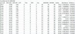
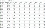
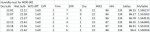
	'Humidity at whole degree seperation for tempreture from 18 to 30 degC | 0 to 5 deg seperation
	
		n0:  '18 point0 {0,1,2,3,4,5} degC
	
	lookup diff, (100,91,82,73,65,57),RH 'dry to wet bulb diffrence whole degree 1 to 5 diffrence
	
	if err =0then		
	RH=RH-RH1
	elseif err=1 then	
	RH=RH+RH1
	endif		
	return
	
	n1:   '19 point1
	
	lookup diff,(100,91,82,74,66,58),RH 
			
	if err=0 then		
	RH=RH-RH1
	elseif err=1 then	
	RH=RH+RH1
	endif		
	return
	
	n2:  
		
	lookup diff,(100,91,83,74,67,59),RH   '20 point2
	'lookup trim,(0,1,2,3,4,4,5,6,7,8),RH1		
	if err=0 then		
	RH=RH-RH1
	elseif err=1 then	
	RH=RH+RH1
	endif		
	return
	
	n3: '21 p3
	
	lookup diff,(100,91,83,75,67,60),RH
	'lookup trim,(0,1,2,3,4,4,5,6,7,8),RH1		
	if err=0 then		
	RH=RH-RH1
	elseif err=1 then	
	RH=RH+RH1
	endif		
	return
	
	n4:' 22  p4
	
	lookup diff,(100,92,83,76,68,61),RH
	'lookup trim,(0,1,2,3,4,4,5,6,7,8),RH1		
	if err=0 then		
	RH=RH-RH1
	elseif err=1 then	
	RH=RH+RH1
	endif		
	return
	
	n5:' 23  p5
	
	lookup diff,(100,92,84,76,69,62),RH
	'lookup trim,(0,1,2,3,4,4,5,6,7,8),RH1		
	if err=0 then		
	RH=RH-RH1
	elseif err=1 then	
	RH=RH+RH1
	endif		
	return
	
	n6: '24  p6
	
	lookup diff,(100,92,84,77,70,63),RH
	'lookup trim,(0,1,2,3,4,4,5,6,7,8),RH1		
	if err=0 then		
	RH=RH-RH1
	elseif err=1 then	
	RH=RH+RH1
	endif		
	return
	
	n7:  ' 25  p7
	
	lookup diff,(100,92,85,77,70,63),RH
	'lookup trim,(0,1,2,3,4,4,5,6,7,8),RH1		
	if err=0 then		
	RH=RH-RH1
	elseif err=1 then	
	RH=RH+RH1
	endif		
	return
	
	n8:' 26  p8
	
	lookup diff,(100,92,85,78,71,64),RH
	'lookup trim,(0,1,2,3,4,4,5,6,7,8),RH1		
	if err=0 then		
	RH=RH-RH1
	elseif err=1 then	
	RH=RH+RH1
	endif		
	return
	
	n9:  ' 27  p9
	
	lookup diff,(100,92,85,78,71,65),RH
	'lookup trim,(0,1,2,3,4,4,5,6,7,8),RH1		
	if err=0 then		
	RH=RH-RH1
	elseif err=1 then	
	RH=RH+RH1
	endif		
	return
	
	n10: ' 28
	
	lookup diff,(100,93,85,79,72,66),RH
	'lookup trim,(0,1,2,3,4,4,5,6,7,8),RH1		
	if err=0 then		
	RH=RH-RH1
	elseif err=1 then	
	RH=RH+RH1
	endif		
	return
	
	n11:  ' 29
	
	lookup diff,(100,93,86,79,73,66),RH
	'lookup trim,(0,1,2,3,4,4,5,6,7,8),RH1		
	if err=0 then		
	RH=RH-RH1
	elseif err=1 then	
	RH=RH+RH1
	endif		
	return
	
	n12: ' 30
	lookup diff,(100,93,86,79,73,67),RH
			
	if err=0 then		
	RH=RH-RH1
	elseif err=1 then	
	RH=RH+RH1
	endif		
	return
	
	n13: ' 31
	lookup diff,(100,93,86,80,74,68),RH
			
	if err=0 then		
	RH=RH-RH1
	elseif err=1 then	
	RH=RH+RH1
	endif		
	return
	
	n14: ' 32
	lookup diff,(100,93,87,80,74,68),RH
			
	if err=0 then		
	RH=RH-RH1
	elseif err=1 then	
	RH=RH+RH1
	endif		
	return
	
	n15: ' 33
	lookup diff,(100,93,87,81,75,69),RH
			
	if err=0 then		
	RH=RH-RH1
	elseif err=1 then	
	RH=RH+RH1
	endif		
	return
	
	n16: ' 34
	lookup diff,(100,93,87,81,75,69),RH
			
	if err=0 then		
	RH=RH-RH1
	elseif err=1 then	
	RH=RH+RH1
	endif		
	return
	
	n17: ' 35
	lookup diff,(100,94,87,81,75,70),RH
			
	if err=0 then		
	RH=RH-RH1
	elseif err=1 then	
	RH=RH+RH1
	endif		
	return
The results after a lot of playing around with are out performing the 4000 001 geting results at a respectable <4% out

graph showing honeyaxe against table values from the sugertech pycometric calculator

picaxehumgraph.jpg

and the graph of the honeywell against table values will ad them as only allowed 2 images per post

regards
john
 
Last edited:

johnlong

Senior Member
Hi part 2

graph of honeywell against table values

honeygraph.jpg

and the collected data on the uSD datalogger in excel

picaxehumidexcel.jpg

regards
john
 

MFB

Senior Member
I'm still intrigued as to why you were unable to achieve acceptable results from the Honeywell sensor. The only problem that I have found with this device was noise pickup at the ADC input,and that was easily reduced by a low-pass RC filter between the sensor output and PICAXE.
 

hippy

Technical Support
Staff member
There seems to be a potential bug in the code in post #23.

'Temp2' is used as a temporary variable in determining wet and dry temperature ...

Code:
trim=b31-48 'Dry bulb 1st decimal place
temp2=b30-48 'second decimal place rounded up or down for dry bulb
if temp2>= 5 then 'used to determine if dry greater than wet
And 'temp2' remains set to whatever the above calculation leaves it at when you come to accumulate your ten humidity sensor readings ...

Code:
for b0= 0 to 9	 
    readADC A.1, hum
    hum=hum-42*100/157 
    Temp2=Temp2+hum
    pause 80      
next b0 
hum=Temp2/10
temp2=0
You are zeroing 'temp2' after the accumulation when it should be zeroed before that starts.

It looks like 'Temp2' in the wet and dry calculations can only hold a value 0 to 9, and you divide 'temp2' by 10 at the end of accumulation so it should have little effect, but it could have some effect.
 

johnlong

Senior Member
Thanks for that Hippy
Late night typing error. Altered the code to clear Temp2 to 0 before the reading of the HIH and altered the loop to 0 to 10
You were right did not alter the results significantly (only 2 bugs this time not a whole code full)
Altered the offset for the HIH to -26*100/157 which is producing better results
MFB you say had no problem but had to add low pass RC filter to obtain exceptable results could you supply details of the RC filter that you used

The aim of the honeyaxe hygromiter was to automate the determination of the amount of error or not with the HIH or any other such sensor
to compare the results and make a determination as to the effectiveness of the sensor (s) over a period of time and diffrent
tempreture bands in making an assesment of the sensor accuracy
With a broader sample over longer time period this can be done more effectivly

Had a look on google for a calculation to put into excel to deal with the table values and came across the following (originally for degF)
=SUM(((100*((EXP(((16.78*(WB-116.9)/((WB+237.3)))-(101.325)*(DB-WB)*(0.00015)*(1+(0.00115)))))))))/(EXP(((16.78*(DB-116.9)/((DB+237.3))))))
It is not a 100% accurate but if you roundup the results it reduces the error to be close enough and save alot of time clicking between
web pages and typing in
regards
john
 

hippy

Technical Support
Staff member
altered the loop to 0 to 10
That will now be taking 11 samples, not 10. Either "0 to 9" or "1 to 10", or you have to divide by 11.

Altered the offset for the HIH to -26*100/157 which is producing better results
So this means that you have two humidity sensors which are not performing as per the datasheet. That seems highly unlikely to me, suggests there's a more fundamental problem somewhere.

I suspect fudging things and then applying more fudges on top by way of compensation may get things appearing to work, but I would suspect there will be errors appearing in other circumstances.
 

eggdweather

Senior Member
I would remove the sensor and replace it with a known voltage source (perhaps low values potential divider across the supply) and see if the noise problem exists, if so then it's not the sensor, most likely a quality of power supply or grounding or environment (electrical noise) issue.
 

johnlong

Senior Member
Hi All
Sorry Hippy misinterpred your 0 to 9 comment as only taking 9 sample returned to 0 to 9
The picaxe circuit creator does state that you may have to play around with the offset
maybe not this much
The power supply is from a USB port off the lap top and reading a steady 4.87V via the multimeter
Its reselution is only to 2 decimal places

These are the latest results with the altered offset
-28offset.jpg

At this offset it seem much more stable and within the ranges specified in the spec sheet but will let it run all night
to see how it varies throughout the night
Will knock together a potential divider as eggdweather sugests could you recomend some vaules for the resistors
if its not to much trouble
regards
john
 

hippy

Technical Support
Staff member
TBH, the only useful readings for diagnosing the problem are single raw ADC readings from the HIH, without any averaging or any other processing, along with what the actual %RH was for that reading.
 

hippy

Technical Support
Staff member
There is definitely something not right. For your ~86%RH the module should be outputting around 3.4V, which should read around 177 from the ADC. Your around 134 is about 2.6V. That's a 0.8V difference.

Everything I have read seems to suggest the sensors are reasonably accurate within their expected tolerances.

Could it be that your determined %RH is actually wrong ? I know nothing about wet and dry bulbs. Is there any way to check the determined %RH is actually what it is.
 
Last edited:

hippy

Technical Support
Staff member
Using the equations in the datasheet, 86%RH should be giving an ADC reading of around 177.

The offset to subtract from an ADC reading should also be around 41.

There seem to be two ways to calculate %RH from the ADC reading -

rh = ( adc / 1.581 ) - 25.8

rh = ( adc - 40.8 ) * 0.632558

And 100/157 is 0.6369, so the original rh=adc-41*100/157 would seem about right.

I would personally try the following as it may be more accurate -

Code:
; rh = ( adc / 1.581 ) - 25.8
; rh = ( ( adc / 0.1581 ) - 258 ) / 10
; rh = ( ( adc * 6.32511 ) - 258 ) / 10

rh = adc * 6
rh = adc ** 21306 + rh - 258 / 10
 

johnlong

Senior Member
Thanks you both for that
That chart was most illuminating looks like magnesium chloride is a good option
for determining a low steady RH 32%, had a quick read around google and you use it just like the salt method
and like salt not that tempreture sensitive
So just ordered a bag of food grade of e**y.
with 2 ponts of refrence and the 2 aporoaches to deterining the offset
looking good.
regards john
 

MFB

Senior Member
Sorry for delay but only just seen your request for RC filter details. Only two components needed. A 10K resistor between the output of the sensor and the PICAXE adc input, plus a capacitor to ground. The capacitor value is a compromise between noise reduction and response time. See http://www.ekswai.com/en_lowpass.htm
 

Goeytex

Senior Member
One of my early Picaxe projects was an egg incubator. I used a Honeywell HIH-4000 sensor and had no issues with stability or accuracy. Unfortunately I no longer have the schematic or a sensor to test, but as I understand the datasheet it reads "minimum load" of 80K. It does not say "minimum resistance" or "minimum load resistance".

"Load" increases as resistance decreases, so I take this to mean that there must be 80K or less resistance to stabilize the circuit. I do not read this as the resistance cannot be less than 80K or resistance must be greater than 80K. That would mean that the sensor could not supply more than about 35 micro-amps of current with an output of 3.0V. This seems rather unrealistic and does not fit well with the minimum supply current specification of 200 microamps.

For testing I would place a 100K Pot (connected as a variable resistor) from Sensor Out to Ground. Then test at 80K, 47K, & 22k and see how circuit responds. ( Or just use fixed resistors). If the ambient temperature is close to 25c then at some point the output voltage should closely match the published specs given the known relative humidity.

Also, for validation, the sensor/ Picaxe testing should be done on a breadboard with nothing else connected and with bare minimum code. The sensor ground, and Picaxe ground should be tied together at a common point (star grounding).
 

Pongo

Senior Member
One of my early Picaxe projects was an egg incubator. I used a Honeywell HIH-4000 sensor and had no issues with stability or accuracy. Unfortunately I no longer have the schematic or a sensor to test, but as I understand the datasheet it reads "minimum load" of 80K. It does not say "minimum resistance" or "minimum load resistance".

"Load" increases as resistance decreases, so I take this to mean that there must be 80K or less resistance to stabilize the circuit. I do not read this as the resistance cannot be less than 80K or resistance must be greater than 80K. That would mean that the sensor could not supply more than about 35 micro-amps of current with an output of 3.0V. This seems rather unrealistic and does not fit well with the minimum supply current specification of 200 microamps.
Earlier this year I asked Honeywell Tech Support to clarify whether that "80K minimum load" was a min or max resistance. The email response was;

"Thank you for your interest in Honeywell Sensing & Productivity Solutions.
The Application Engineer advised: 80K minimum resistance, could be 100K.
If you have any questions or need further assistance, please contact us."
 

Goeytex

Senior Member
Thanks, I was about to shoot off a note to Honeywell to clarify the ambiguous use of " minimum load" ..

Even then you get an ambiguous answer. Does that then mean that the minimum resistance "could be" 100K ?, Seems to me then that it might be a good idea to buffer the output with a good OPAMP. And the cost goes up even more. These are not cheap and is why I abandoned them.

Might be a better idea to use something like a Silicon labs Si7021 that includes both temperature and humidity with I2C output.
 
Top