I have been toying with some flash ideas to go with PICAXE flash controller I built a while back.
Air gap flash does keep comping up, but I came across something called a vela one.
https://www.vela.io/vela-one-high-speed-flash
now while relatively cheap (£787) and a fair amount less dangerous than the 20+kv of an air gap flash, I wondered how they got what they needed. they apparently use COB LEDs but they give no details on how its driven.
a picaxe @ 64mhz can get close with a 0.625us pulsout( length of flash could be varied too), which should be fast enough for just about everything but the fastest bullets. I have been thinking about using some CREE LEDs as they are extremely bright. I have a torch with 7 in and is rated for just 9000 lumen, something short of velas' claimed 1,000,000 lumens.
I have not looked into driving CREE LEDs as yet, but most have a very high ESD rating (often more than 2000v), so the current thinking is get hold of some and drop double rated voltage through them which should get pretty close.
Any thoughts? If the LEDs can just take power strait of the rail (negating drive issues with them), what will be needed to drive a high current load of a dozen or more LEDs for such a short period of time with the shortest possible rise and fall times - I know a large capacitor will be need on the rail to keep things going - maybe charge a large capacitor and drop the current through a power mosfet of some description. I am open to ideas, not just for creating the desired output but for features to try and include, figuring a charge/ready indicator would be a good start
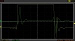
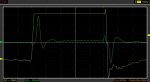
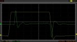
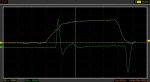
from vela
Air gap flash does keep comping up, but I came across something called a vela one.
https://www.vela.io/vela-one-high-speed-flash
now while relatively cheap (£787) and a fair amount less dangerous than the 20+kv of an air gap flash, I wondered how they got what they needed. they apparently use COB LEDs but they give no details on how its driven.
a picaxe @ 64mhz can get close with a 0.625us pulsout( length of flash could be varied too), which should be fast enough for just about everything but the fastest bullets. I have been thinking about using some CREE LEDs as they are extremely bright. I have a torch with 7 in and is rated for just 9000 lumen, something short of velas' claimed 1,000,000 lumens.
I have not looked into driving CREE LEDs as yet, but most have a very high ESD rating (often more than 2000v), so the current thinking is get hold of some and drop double rated voltage through them which should get pretty close.
Any thoughts? If the LEDs can just take power strait of the rail (negating drive issues with them), what will be needed to drive a high current load of a dozen or more LEDs for such a short period of time with the shortest possible rise and fall times - I know a large capacitor will be need on the rail to keep things going - maybe charge a large capacitor and drop the current through a power mosfet of some description. I am open to ideas, not just for creating the desired output but for features to try and include, figuring a charge/ready indicator would be a good start
from vela
After months of experimenting with different circuits and LEDs, we have built a circuit that drives nine LEDs up to 20 times brighter than rated, without damaging them or overheating