Adding PWM speed control to Linear Actuators for TV control

joshzstuff

New Member
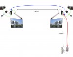
The project I'm working on is to open and close a set of TVs mounted on a hinge.
They are installed in a church stage, they fold against the wall when not in use and the actuators push them to face the audience when needed. (then pull back to the wall)
I didn't realize that I needed speed control, so I simply installed them controlled by a double pole relay with a reversing circuit. A single pole switch loop controls the actuators remotely.
The relays work fine, however the TVs, moving at full speed come to an abrupt stop, so I'd like to add a PWM circuit to slow them at the end of their extension.

Here is what my plan is:
I want to place a mosfet or some other driving circuit between the power supply and the relay. And control it with a micro controller (Pic/ Arduino)
I can program the speed control based on simply timing, or I can use a Potentiometer connected to the moving parts as a feedback.

I know that I could also replace the relays with H-bridge motor drivers, however if I can source the parts to augment the current setup it would seem simpler.

Specs and distances:
The actuator runs at 5 amps but peeks @ 8amps at startup.
https://www.amazon.com/gp/product/B017S3H05E/ref=oh_aui_detailpage_o06_s00?ie=UTF8&psc=1

I have 12 guage -2 conductor wire between the tv locations to send the switch positions simultaneously from the switch which is connected to the first TV location relay.

Can anyone recommend either discreet components for the motor driver, or else a board I can purchase to handle the load from the actuators?
I'm feel I should have something rated for 8-10 Amps.

Please let me know if I forgot to add any important details.

Thank You!
 
Last edited:

premelec

Senior Member
Spec says 12v DC motor - I'd just try reducing the voltage to see if they slow appropriately to what you want - either by using a variable DC supply or PWM - at only 5 amps you don't need very heavy wire and if only occasional use you don't need efficiency so you could use resistors in series with motors or a power transistor on a heat sink etc... test what if you just run the motors from lower voltage throughout your actuation. If you are worried about stall current on end mechanical stop resistor in series will 'soften' the supply - or you can use a constant current drive ... these would also help reduce startup surge - see what voltage they will start at etc... more data needed... ;-0
 

joshzstuff

New Member
Spec says 12v DC motor - I'd just try reducing the voltage to see if they slow appropriately to what you want - either by using a variable DC supply or PWM - at only 5 amps you don't need very heavy wire and if only occasional use you don't need efficiency so you could use resistors in series with motors or a power transistor on a heat sink etc... test what if you just run the motors from lower voltage throughout your actuation. If you are worried about stall current on end mechanical stop resistor in series will 'soften' the supply - or you can use a constant current drive ... these would also help reduce startup surge - see what voltage they will start at etc... more data needed... ;-0
Thank you for your comments premelec!
I am using a micro-controller because I need full current at the start and it needs to come to a gradual stop.
I may use limit switches to sense the end of the opening and closing cycles.
The actuators have built in limit switches at the beginning and end of the stroke.
Can you list an example of a 'mechanical stop resister'?

Thanks!
 

premelec

Senior Member
Well... it's 1 AM and I don't recall mechanical stop R ;-0 however probably just a current limiting resistor for when the end is reached... Actually I'd probably use a current limited supply... Is your supposition that you need full current at the start from some empirical test or just a guess? Ordinarily a DC motor can start at lower voltage and hence current. You can test end stops with current sense units [could be hall effect or small resistor] as the current will increase a lot when hit mechanical end - or with current limited supply voltage will go down when ends hit... As long as you've arranged to use full actuation of the unit internal limit switches should work. Caution as to just what they do - I presume somehow you can still reverse polarity of drive but this might not be the case. Likely they don't actually cut the drive V but just signal end... or not... ;-0 The gradual stop could conceivably just be a capacitor and MOSFET setup tp reduce voltage as capacitor discharges at some trigger point... whatever works for you. Using PWM can cause noise [audible] in some applications so best to bench test.
 

joshzstuff

New Member
Some linear actuators have an in-built potentiometer to sense position. If you can find one of the correct travel, that would allow you to run full speed and then do a slowdown as the potentiometer approaches the end of it's resistance range.
Yes wapo, however I did not purchase this type as I did not foresee a need for speed control. However I can install my own Pot on the Hinge of the mount for the same effect. I'm looking forward to programming the speed profile!
 

eggdweather

Senior Member
You may find that using satellite dish actuators is much easier as they have limit switches to prevent overrun and have (usually) a reed switch pulse output, so you can count turns or distance moved, they are designed to operate slowly to position a dish not move at high speed.

Satellite actuators have a full set of hinges available and are lower price about $40, also most have adjustable limit switching so you'd really just need to give them power and they slowly move out, Apply power again to retract, obviously controlled power enabled precise positioning.
 

erco

Senior Member
That's a lot of current! You can certainly make it into a PWM project, and will be a fun/educational/frustrating experience if you're not an ace at it already. Good on ya.

Alternatively, here's a quick way out just using hardware & empirical testing. Add a high-current SPDT limit switch near the end of travel on each end, where you want it to slow down from full speed. This switches (high current) diodes in & out of the motor circuit. You could either completely switch the motor off and let it coast to the end point, or drop the voltage through a string of diodes or a power resistor. In all cases, you'll need another single diode (reverse-biased) across the open switch/diode string/resistor to get the motor moving in the reverse direction.

As promised, it will take some experimenting with switch location and #diodes/resistor value to nail it.
 

joshzstuff

New Member
That's a lot of current! You can certainly make it into a PWM project, and will be a fun/educational/frustrating experience if you're not an ace at it already. Good on ya.

Alternatively, here's a quick way out just using hardware & empirical testing. Add a high-current SPDT limit switch near the end of travel on each end, where you want it to slow down from full speed. This switches (high current) diodes in & out of the motor circuit. You could either completely switch the motor off and let it coast to the end point, or drop the voltage through a string of diodes or a power resistor. In all cases, you'll need another single diode (reverse-biased) across the open switch/diode string/resistor to get the motor moving in the reverse direction.

As promised, it will take some experimenting with switch location and #diodes/resistor value to nail it.
Thanks erco!
That is a cool solution to the problem, i've never used SPDT limit switches before!
I should mention that I already have a great deal of parts and installation that keeps me from scrapping this angle for a ground- up solution.
(These actuators do not coast, they need to be set at a minimum voltage at the end of the opening cycle until they reach the internal limit switches.)
I am trying to augment the system already installed, so some of these creative alternatives I honestly did not even think of.
Thanks for your help.
PicAxe Coding to follow!
 

joshzstuff

New Member
I'm rusty at PicAxe Basic, Help please!

My first picaxe project in 4 years!
There is a syntax error on line 13 that is, well, driving me 'buggy' ;)

Code:
init:                                     
	symbol Motor =1                 			;Rename port 1 to Motor
      symbol Counter=b0                  			 ;Rename b0 variable to Counter
	symbol Closed_Limit = C.3				;Closed limit switch input renamed
	symbol Full_Open_limit = C.4				;Fully opened limit switch input renamed
	
TV_Closed:								;Begining state, motor is fully closed
	

TV_Opening:

		
     	If Closed_Limit = low then pause 3500		;Timer starts for correct motor slowdown timing after limit opens
	endif 
									
		
Speed_Control:                                     	;Speed Control at end of the opening cycle
	
           For Counter = 255 to 50 step -1 		;Start with a full on duty cycle and decrease
                   PWM 1, Counter, 1			;Send one puls out on port 1 with decreasing duty cycle
			;pause 5 					;* increase the fade time adjustmen**
		next Counter                   		;Increment Counter and loop back                              
                 PWM 1, 50					;remain at minimum speed until limit reached
	if Full_Open then goto Close_TV			;limit switch resets program to prepare for closing cycle

Close_TV:								;TV closes at full speed
		PWM 1, 255						;PWM set to maximum for Closing cycle
		
	if Closed_Limit = high then goto TV_Closed	;Closed limit resets the program loop
TV_PicAxe.JPG

Thank You!
 

hippy

Technical Support
Staff member
symbol Closed_Limit = C.3
If Closed_Limit = low then

You need to to use "pinC.3" rather than just "C.3" to read the level status on that pin. Likewise with Full_Open_limit.

Note you have "Full_Open_limit" as a symbol but use "Open_limit" in your IF statement.

You also compare =low and =high; those should be =0 and =1.

Also "if Full_Open then" needs to have an =1 ( or =0 ).
 

lbenson

Senior Member
When testing an input pin, you have to use the pinX.n notation form, so

symbol Closed_Limit = pinC.3 ;Closed limit switch input renamed

And then (because "low" is a command)
Code:
  If Closed_Limit = 0 then 
    pause 3500		;Timer starts for correct motor slowdown timing after limit opens
  endif
 
Top