An interesting observation, but my understanding is that these are rated for protection against damage from static, not the relatively high currents that are available from back-EMF events. I was under the impression that these internal diodes could be blown by back-EMF currents; perhaps Hippy or others who are also more knowledgeable could advise?Diodes are in the internal structure of the picaxe output pin
View attachment 21614
Can the 14m2 directly control a latching relay with a 5V 20ma coil?
- Thread starter wapo54001
- Start date
Jeremy Harris
Senior Member
Depends mainly on two factors, the capacitor inductance (which may be significant for a wound electrolytic) and the capacitor equivalent series resistance at high frequencies, plus a bit of luck, I think.Thanks for the reply, I've been using a single 08M2 pin with a single coil latching relay with a rather large capacitor -- 100uF -- and it works perfectly. It seems to me that charging of the series capacitor happens gradually through coil resistance and also discharges gradually through the same resistance. Couldn't see the point of a diode and also couldn't see how a diode could be inserted and still have the circuit work . . .
It may well be that the internal clamp diodes on the pins of the Picaxe are up to conducting away any very short duration, high amplitude, spikes, or they may not. They don't have a very high reverse voltage rating, IIRC, and it may well be possible to see very short duration transients of a few tens of volts, perhaps enough to punch through the internal clamp diodes.
Given that a diode that will be well up to the job costs around a penny, my view is that it's better to fit one or two than run the risk. I've left such diodes off before and things have worked OK, but wouldn't like to recommend it as good practice, for a few reasons. Firstly, it might well be just luck that it works OK without damage; there may be enough series inductance or parallel capacitance, to snub any spike. Secondly, it might work well for a time, then as the capacitor ESR gets higher with age, any spike voltage gradually increases until failure becomes more probable. Finally, continually stressing the clamp diode with very short duration spikes might eventually cause a punch-through failure; I don't know just how robust the clamp diode are.
I have had two sets of these low current 5 V latching relays running from a Picaxe for some months now, switching twice a day, and they seem very reliable, but I do have 1N4148 diodes to protect the Picaxe pins. Maybe I could get away without them, but their cost is so trivial compared to the other components on the board that there seemed no harm in adding them, even if it is considered to be a bit of a belt-and-braces solution..
Hi,
In this particular application, the current in the inductor must be initially flowing in one of the output FETs of the PICaxe. If / when that FET switches off, the inductor "insists" that the current finds an alternative path (by generating a very high voltage if that is necessary). The purpose of the flywheel diode is to "catch" the voltage at a level that the chip can tolerate. So the current rating of the diode does not need to exceed the current rating of the PIC's pin-driver FETs and the reverse voltage does not need to exceed the (maximum rated) rail-to-rail supply voltage (plus the forward voltage of the other diode).
If we look at the Absolute Maximum ratings of the relevant Microchip data sheet (section 30.) we see:
Clamp current, IK (VPIN < 0 or VPIN > VDD)..............................20 mA
Maximum output current sunk by any I/O pin...............................25 mA
Maximum output current sourced by any I/O pin ..........................25 mA
To be pedantic, the chip might (legitimately) deliver 25 mA, which exceeds the internal diode rating, so the external diodes are necessary,")
However, AFAIK (but my experience was entirely with bipolar ics), the lower "protection" diodes are "substrate" diodes which are intrinsic in the manufacturing process, cannot be avoided and are relatively "beefy". So a large underswing voltage will not occur, except by destroying the bond wire. Also, the PIC{axe} pull-up (source) FETs are rather "weak" and are unlikely to deliver much over 20 mA (at best), so the lower external diode is probably not needed.
But the pull-down (sink) FETs are more powerful, so there is a real risk that the current could significantly exceed 20 mA (the data sheet characterises them to over 50 mA - see Figure 31-42). Also, the overswing diode is added only for "electrostatic" protection, so an external positive overswing diode probably should be included.
It's also worth noting that (whether the external diode is present or not) the overswing diode feeds current into the power supply rail. Therefore, an adequately-sized supply decoupling capacitor is essential to prevent the whole chip / circuit being damaged by excessive voltage on the supply rail.
Cheers, Alan.
In this particular application, the current in the inductor must be initially flowing in one of the output FETs of the PICaxe. If / when that FET switches off, the inductor "insists" that the current finds an alternative path (by generating a very high voltage if that is necessary). The purpose of the flywheel diode is to "catch" the voltage at a level that the chip can tolerate. So the current rating of the diode does not need to exceed the current rating of the PIC's pin-driver FETs and the reverse voltage does not need to exceed the (maximum rated) rail-to-rail supply voltage (plus the forward voltage of the other diode).
If we look at the Absolute Maximum ratings of the relevant Microchip data sheet (section 30.) we see:
Clamp current, IK (VPIN < 0 or VPIN > VDD)..............................20 mA
Maximum output current sunk by any I/O pin...............................25 mA
Maximum output current sourced by any I/O pin ..........................25 mA
To be pedantic, the chip might (legitimately) deliver 25 mA, which exceeds the internal diode rating, so the external diodes are necessary,
However, AFAIK (but my experience was entirely with bipolar ics), the lower "protection" diodes are "substrate" diodes which are intrinsic in the manufacturing process, cannot be avoided and are relatively "beefy". So a large underswing voltage will not occur, except by destroying the bond wire. Also, the PIC{axe} pull-up (source) FETs are rather "weak" and are unlikely to deliver much over 20 mA (at best), so the lower external diode is probably not needed.
But the pull-down (sink) FETs are more powerful, so there is a real risk that the current could significantly exceed 20 mA (the data sheet characterises them to over 50 mA - see Figure 31-42). Also, the overswing diode is added only for "electrostatic" protection, so an external positive overswing diode probably should be included.
It's also worth noting that (whether the external diode is present or not) the overswing diode feeds current into the power supply rail. Therefore, an adequately-sized supply decoupling capacitor is essential to prevent the whole chip / circuit being damaged by excessive voltage on the supply rail.
Cheers, Alan.
* AllyCat wrote:
In this particular application, the current in the inductor must be initially flowing in one of the , the current in the inductor must be initially flowing in one of the output FETs of the PICaxe. If / when that FET switches off, the inductor "insists" that the current finds an alternative path (by generating a very high voltage if that is necessary). The purpose of the flywheel diode is to "catch" the voltage at a level that the chip can tolerate. ...
Very well written.
* To consideration on paralel diodes:
wapo54001 has a 5V/250ohm relay with a rated current of 20mA.
When the output FET turns off then the 20 mA induced current in the inductor starts to flow through the internal diodes. Max. current of 20 mA is not exceeded. Therefore no external parallel diodes are needed.
However, if someone wants increased reliability or industrial grade reliability, it is better to add external protective diodes.
But be careful, the diodes must be Schottky. Why? The external schottky diode has 0.4-0.5V at 20mA.
The internal diode leads a negligible current at such a voltage.
* Here are some data from the PIC datasheet - I think they are useful to everyone.

picture 1. 14M2 - Electrical specifications: Absolute maximum ratings

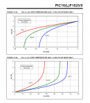
picture 2. 14M2 - VOH vs. IOH and VOL vs IOL
In this particular application, the current in the inductor must be initially flowing in one of the , the current in the inductor must be initially flowing in one of the output FETs of the PICaxe. If / when that FET switches off, the inductor "insists" that the current finds an alternative path (by generating a very high voltage if that is necessary). The purpose of the flywheel diode is to "catch" the voltage at a level that the chip can tolerate. ...
Very well written.
* To consideration on paralel diodes:
wapo54001 has a 5V/250ohm relay with a rated current of 20mA.
When the output FET turns off then the 20 mA induced current in the inductor starts to flow through the internal diodes. Max. current of 20 mA is not exceeded. Therefore no external parallel diodes are needed.
However, if someone wants increased reliability or industrial grade reliability, it is better to add external protective diodes.
But be careful, the diodes must be Schottky. Why? The external schottky diode has 0.4-0.5V at 20mA.
The internal diode leads a negligible current at such a voltage.
* Here are some data from the PIC datasheet - I think they are useful to everyone.
picture 1. 14M2 - Electrical specifications: Absolute maximum ratings
picture 2. 14M2 - VOH vs. IOH and VOL vs IOL
Attachments
-
 48.2 KB Views: 63
 -
 74.6 KB Views: 63
Last edited:
PhilHornby
Senior Member
Practical measurements...
I dug a latching relay out of an old (3V powered) Drayton Central Heating thermostat. According to my 'Component Tester', it has a DC resistance of just 4.7Ω and an inductance of 730µH (so admittedly, quite a bit different to the other examples discussed to date).
What I found was, when +ve voltage is applied to the series circuit, the full supply voltage appears instantly across the relay and decays exponentially. At the same time, the voltage across the capacitor rises exponentially to the supply voltage. Eventually, the current (to all intents and purposes) ceases to flow.
When the +ve supply is removed and that point taken to Earth, the voltage stored in the capacitor immediately appears across the relay and decays exponentially. The voltage across the capacitor likewise decays away exponentially, until the current eventually ceases to flow.
So long as the current flow is not interrupted before the stable-state is reached, I was unable to generate any 'spikes' as such. There was only the briefest sign of oscillation/ringing occurring. (Supply voltage used was 5VDC and the capacitor was 470µF).
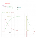
I found an online circuit emulator that was quite useful for investigating some aspects of this circuit @ http://www.falstad.com/circuit/
Scope traces:-
Pin goes HIGH - capacitor charging

Pin goes LOW - capacitor discharging

This question intrigued me, since a relay and capacitor in series, form an R-L-C circuit, which has the potential for generating some unexpectedly high voltages (such as in my recent AC motor experiments). There are web resources that suggest phenomena such as the capacitor charging to double supply voltage, and/or the circuit going into oscillation are possible...In the case of a latching relay, there is no current flowing through the coil when the power sourced is switched between +5 and ground and therefore no magnetic field to collapse and cause the EMF. Also, the resistance of the coil will limit current flow to a maximum of 20ma.
Is a protective diode still required?
I dug a latching relay out of an old (3V powered) Drayton Central Heating thermostat. According to my 'Component Tester', it has a DC resistance of just 4.7Ω and an inductance of 730µH (so admittedly, quite a bit different to the other examples discussed to date).
What I found was, when +ve voltage is applied to the series circuit, the full supply voltage appears instantly across the relay and decays exponentially. At the same time, the voltage across the capacitor rises exponentially to the supply voltage. Eventually, the current (to all intents and purposes) ceases to flow.
When the +ve supply is removed and that point taken to Earth, the voltage stored in the capacitor immediately appears across the relay and decays exponentially. The voltage across the capacitor likewise decays away exponentially, until the current eventually ceases to flow.
So long as the current flow is not interrupted before the stable-state is reached, I was unable to generate any 'spikes' as such. There was only the briefest sign of oscillation/ringing occurring. (Supply voltage used was 5VDC and the capacitor was 470µF).
I found an online circuit emulator that was quite useful for investigating some aspects of this circuit @ http://www.falstad.com/circuit/
Scope traces:-
Pin goes HIGH - capacitor charging
Pin goes LOW - capacitor discharging
Last edited:
rq3
Senior Member
A Picaxe pin can source 5 volts at zero amps, or can source 20 mA at a voltage dependant upon its internal mosfet. It cannot do both at the same time (source 20 mA while maintaining 5 volts).I found a post that describes the maximum current capability of pins on the various Picaxe chips here: http://www.picaxeforum.co.uk/showthread.php?11963-PICAXE-I-O-Current-Capability
However, in other posts I have found discussions of a maximum current at 20 milliamps instead of 25 milliamps.
At the moment I am interested in the 14M2, and I would like to drive this latching relay http://www.digikey.com/product-search/en/relays/signal-relays-up-to-2-amps/1049448?k=kemet+relay&k=&pkeyword=kemet+relay&pv675=3&pv72=1&pv1410=13&pv69=80&mnonly=0&newproducts=0&ColumnSort=0&page=1&stock=1&quantity=0&ptm=0&fid=0&pageSize=25 directly from a Picaxe pin set high, using a capacitor on the low side of the relay coil to store energy to return the relay when the pin is set low.
The post above states that each pin can source or sink 25 milliamps, and this relay draws 20 milliamps at 5vdc (coil resistance = 250 ohms) only long enough to charge the capacitor. When the capacitor is charged, current draw drops dramatically and is no longer an issue. I expect the 20 milliamp draw will be very transitory.
Question I have is, is it safe in the long term to run this relay directly from the 14M2 pin? If 20ma is the maximum, this is working right at the edge, if it's 25ma, then I believe that is adequate headroom for this circuit.
If this isn't going to work I can go to a non-latching relay but I would prefer not to run 20ma continuously through the relay which will be mostly in a steady-state ON.
Years ago I measured the source impedance of a 20M2 source (high) at 90 ohms, while the same pin sinking (low) was about 30 ohms. These values are highly variable, and depend upon how the silicon is doped during the manufacture of the PIC itself.
But, assuming that the internal impedance of the mosfet is indeed 90 ohms when sourcing current at 5 volts, a 90 ohm load would drop the pin to 2.5 volts, and the picaxe internals would be sourcing almost 28 mA. Not good!
So, still assuming that the Picaxe is operating at 5 volts, you would need a total pin impedance of 250 ohms to limit the pin current to 20 mA. Minus the 90 ohm internal impedance, the pin would safely drive a load of 160 ohms to 3.2 volts.
Your 250 ohm coil impedance is perfectly safe, even if driven continuously, and will have a pin voltage of about 3.7 volts. If that is enough to guarantee switching of your relay, you are home free
rq3;314697 So said:That's a great bottom line. And, I must say that I've learned an awful lot from this thread which started out with what I thought was a simple question! LOL Thanks to all for the great learning experience!
PhilHornby
Senior Member
I'm having fun learning to use Circuit Emulators ...Thanks to all for the great learning experience!
I've had a go at emulating a Picaxe driving your relay (I had to guess at the Relay's Inductance).
See HERE
rq3
Senior Member
That's cool! It might give more realistic results if the picaxe "internal" 5 volt source had a current capability of 25 mA and an impedance of zero (the source impedance is already modeled by the 90 and 30 ohm mosfet resistors).I'm having fun learning to use Circuit Emulators ...
I've had a go at emulating a Picaxe driving your relay (I had to guess at the Relay's Inductance).
See HERE
There are quite a few of these simulators out there. One of the best is the old Texas Instruments "Tina-TI". Although it is geared towards TI's own devices, it does allow for import of Spice models, so you can add anything that has a Spice model. And it's free.
Picaxe itself cannot reliably switch this relay model in a capacitor design.
Excessive voltage drop on the output pin will provides for the relay only 5V * 250Ω / (250Ω + 90Ω = 3.7V. Even when 3.7V is near minimum 3.75, the relay have to be at this voltage for min.10ms. But in our circuit the voltage on the relay exponentially decreases.
It is still possible to power the relay through the 74AC IC. The inverters 74AC04 have an output voltage of >4.36V or <0.36V at 24mA and Vcc = 5V.
This corresponds to 27 Ω / 15Ω in the linearized output voltage drop model. Then the relay voltage is 5V*250Ω/(250Ω+27Ω=4.5V in the state H and 4.7V in the state L.
The voltage on the relay decreases exponentially Ure = Ureo * (1 - exp(t/T)), where T is time constant of the relay resistance (plus 74AC output) and the capacitor.
- When Uro = 4.5V and Ure = 3.75V, then t/T is approximately. (1-Ure/Ureo), of which then t/T = 0.16
- According to the datasheet, we must hold the relay voltage at the specified value for time t >= 10 ms. Required time constant T >= 10ms/0.16 = 62.5ms
- Since the total resistance is 250 + 27 = 277Ω and T = R * C, the capacitor should be C> T / R = 62.5ms / 277Ω = 225uF.
- When the ceramics are too expensive, so the tantalum capacitor would be suitable for long-term reliability.
When the time constant is 62.5 ms, you need to keep the relay in a new state approximately in time 3 * T = 200 ms until the capacitor is fully charged / discharged.
It is not the minimal variant, but reliable variant.
pictures:
74AC04 - selected parameters
EC2 relay - selected parameters
LatchRelay&74AC04_schema
LatchRelay&74AC04_diagram

Excessive voltage drop on the output pin will provides for the relay only 5V * 250Ω / (250Ω + 90Ω
= 3.7V. Even when 3.7V is near minimum 3.75, the relay have to be at this voltage for min.10ms. But in our circuit the voltage on the relay exponentially decreases.It is still possible to power the relay through the 74AC IC. The inverters 74AC04 have an output voltage of >4.36V or <0.36V at 24mA and Vcc = 5V.
This corresponds to 27 Ω / 15Ω in the linearized output voltage drop model. Then the relay voltage is 5V*250Ω/(250Ω+27Ω
=4.5V in the state H and 4.7V in the state L.The voltage on the relay decreases exponentially Ure = Ureo * (1 - exp(t/T)), where T is time constant of the relay resistance (plus 74AC output) and the capacitor.
- When Uro = 4.5V and Ure = 3.75V, then t/T is approximately. (1-Ure/Ureo), of which then t/T = 0.16
- According to the datasheet, we must hold the relay voltage at the specified value for time t >= 10 ms. Required time constant T >= 10ms/0.16 = 62.5ms
- Since the total resistance is 250 + 27 = 277Ω and T = R * C, the capacitor should be C> T / R = 62.5ms / 277Ω = 225uF.
- When the ceramics are too expensive, so the tantalum capacitor would be suitable for long-term reliability.
When the time constant is 62.5 ms, you need to keep the relay in a new state approximately in time 3 * T = 200 ms until the capacitor is fully charged / discharged.
It is not the minimal variant, but reliable variant.
pictures:
74AC04 - selected parameters
EC2 relay - selected parameters
LatchRelay&74AC04_schema
LatchRelay&74AC04_diagram
Last edited:
rq3
Senior Member
Folks seem to be assuming that my measured values of Picaxe pin I/O impedance is fixed and reliable. As I stated in my post, it is not. You need to measure your circuit, understand from where the variables arise, and proceed from there. It is not a cut and paste process.Picaxe itself cannot reliably switch this relay model in a capacitor design.
Excessive voltage drop on the output pin will provides for the relay only 5V * 250Ω / (250Ω + 90Ω
It is still possible to power the relay through the 74AC IC. The inverters 74AC04 have an output voltage of >4.36V or <0.36V at 24mA and Vcc = 5V.
This corresponds to 27 Ω / 15Ω in the linearized output voltage drop model. Then the relay voltage is 5V*250Ω/(250Ω+27Ω
The voltage on the relay decreases exponentially Ure = Ureo * (1 - exp(t/T)), where T is time constant of the relay resistance (plus 74AC output) and the capacitor.
- When Uro = 4.5V and Ure = 3.75V, then t/T is approximately. (1-Ure/Ureo), of which then t/T = 0.16
- According to the datasheet, the relay needs a on/off time t >= 10 ms. Required time constant T >= 10ms/0.16 = 62.5ms
- Since the total resistance is 250 + 27 = 277Ω and T = R * C, the capacitor should be C> T / R = 62.5ms / 277Ω = 225uF.
- When the ceramics are too expensive, so the tantalum capacitor would be suitable for long-term reliability.
When the time constant is 62.5 ms, you need to keep the relay in a new state approximately in time 3 * T = 200 ms until the capacitor is fully charged / discharged.
It is not the minimal variant, but reliable variant.
pictures:
74AC04 - selected parameters
EC2 relay - selected parameters
LatchRelay&74AC04_schema
LatchRelay&74AC04_diagram
View attachment 21629 View attachment 21630
It seems that your picaxe has the characteristics of a typical PIC16F1825/9 (see diagram in # 44)Folks seem to be assuming that my measured values of Picaxe pin I/O impedance is fixed and reliable. As I stated in my post, it is not. You need to measure your circuit, understand from where the variables arise, and proceed from there. It is not a cut and paste process.
Yes, you are right. It was not a cut and paste process.