Servo assembly

pkf

Member
Hi,

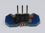
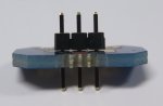
My question concerns how the servo board should be assembled to the rear of the microbot.

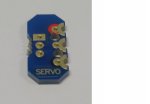
There are 2 sides of the servo board the side with the word 'servo' labelled
With servo label.jpg

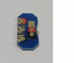
and the side without the word 'servo' labelled
Without SERVO label.jpg

Which side should face up during assembly, or does it matter ? and why ?
 

hippy

Technical Support
Staff member
When attached correctly, the red connector on the add-on aligns with the red connector of the MicroBot main board.

There is an image at the top of page 47 in the BOT120 datasheet which shows how to assemble a servo connector.

The side which faces upwards after assembly is the side without the 'servo' label. The side with the 'servo' label is towards the underneath of the MicroBot.
 

pkf

Member
Thanks. Does this mean that the quarter panel (on page 12) and the servo circuit board share a 'similar' location, one on top of the other at the top of the bric ?
If yes, does the red connector of the quarter panel also align with the red connector of the Microbot main board ?
If the quarter panel and the servo board circuit are assembled, the servo board circuit should be on top of the quarter panel right ?
 

hippy

Technical Support
Staff member
The Quarter Module has nothing to do with the Servo Module.

Solder a 3-pin header to the Servo Module. Connect a 'bric' assembly to it, mate it to the MicroBot, screw it into place. That is all there is to it.
 

pkf

Member
I understand the function of the quarter module is not related to the function of the servo module.

Do we mean that after I have connected the servo module like what you mentioned, I can still connect the quarter module elsewhere ?
 

hippy

Technical Support
Staff member
Yes, once the Line Tracker is assembled using the Quarter Module it can be connected elsewhere to the MicroBot. The red mark on the Quarter Module lines up with the red marking on the MicroBot main board.

The Servo Module would normally be attached to the centre-rear B.0 connection point, the Line Tracker assembly would normally be connected to the centre-front C.2 connection point - That is shown on page 12 of the BOT120 assembly guide and datasheet.
 

pkf

Member
Hi, should the 3 pin header be soldered with the longer leads facing up ?

Based on the accessories range that Picaxe has, can the 3 pin header be used for another assembly other than the servo or it is mainly meant for the servo ?
 

Jeremy Harris

Senior Member
Hi, should the 3 pin header be soldered with the longer leads facing up ?

Based on the accessories range that Picaxe has, can the 3 pin header be used for another assembly other than the servo or it is mainly meant for the servo ?
Have you read the manual for the BOT123? It says this, in a paragraph halfway down the first page:

Servo Module PCB
Place the 3 way header onto the top of the PCB, so that the pins come
out the bottom. Solder in position.
The header connection pins therefore face upwards.
 

pkf

Member
Yes I came across that section too. For my 3 pin header, the pins are held in position by a plastic, one end of the 3 pins are longer measuring from the plastic and the other end of the 3 pins are shorter also measuring from the plastic. In other words, if the header is held upright, the ends of the pins protrude from the top and bottom. What we mean is the shorter ends of the pins go into the servo pcb, and we solder the header and servo together right ?
 

Jeremy Harris

Senior Member
Yes I came across that section too. For my 3 pin header, the pins are held in position by a plastic, one end of the 3 pins are longer measuring from the plastic and the other end of the 3 pins are shorter also measuring from the plastic. In other words, if the header is held upright, the ends of the pins protrude from the top and bottom. What we mean is the shorter ends of the pins go into the servo pcb, and we solder the header and servo together right ?
The header connections are the long pins. If you look, the short pins that go through the PCB and are soldered aren't long enough to go into the servo connector. If you soldered the long side into the board then there would be long pins sticking out through the solder joint and the short pins that are supposed to be soldered in wouldn't be long enough to plug into the servo connector.
 

pkf

Member
Servo board solder to 3 pin header

Hi, before I solder from the bottom of the assembly, I am trying to find out which pin header insertion to the servo board is correct, or it does not matter.
In the 1st picture, the longer pins are facing up (and the shorter pins go through the servo pcb).
Longer pins facing up.jpg
In the 2nd picture, the shorter pins are facing up (and the longer pins go through the servo pcb).
Shorter pins facing up.jpg
 
Last edited:

Jeremy Harris

Senior Member
As answered before in another answer to this same question, the header connector pins need to be upwards, so that the servo connector can plug on to them. What you've shown in your lower picture won't work - try it, the short pins won't be long enough to plug into the servo connector properly. The top picture is the right way around, with the header connector pins able to fit the servo connector.
 

westaust55

Moderator
I have merged pkf's two threads relating to the BOT120 servo module to keep the topic under one thread/heading for continuity
 

pkf

Member
The reason I have chosen to attach pictures this time is because the purely descriptive responses, no matter how well-meaning I received earlier wasn't obvious to me. I get the picture now.
 

Jeremy Harris

Senior Member
One thing worth trying is an experiment when you encounter something like this, as I suggested. Try and plug the servo connector on to the (longer) connector pins of the header and you will find it fits well. Try the same with the short solder pins and you will find that it just doesn't fit properly and most probably won't either make contact or stay in place.
 

pkf

Member
Yes you are right. I don't have a servo connector at the moment but intend to get one and try out.
One more question. How does a complete servo sub-assembly (of the microbot) process commands ? Purely through the commands we program in the Microbot or the use of a device (e.g. remote control) ?
 

westaust55

Moderator
One more question. How does a complete servo sub-assembly (of the microbot) process commands ? Purely through the commands we program in the Microbot or the use of a device (e.g. remote control) ?
That will depend upon how you wish to use the BOT120 and in particular the servo/SRF005.

You could have a program that automatically rotates, as a series of steps/positions, the servo/SRF005 Ultrasonic sensor to detect how far objects are away in various directions and from that the program might automatically determine which way to turn and travel.

Alternatively you could use the IR remote controller (if you have that with the IR receiver) and manually turn the servo motor/ultrasonic sensor to detect and measure a distance.
That could be useful if you also have a separate receiver/display to indicate the actual distance back to you.

Ultimately it will come down to what you want the BOT120 to do and how YOU program it.
 

pkf

Member
Is there an estimated range from the IR remote controller to the microbot unit ? Is the IR remote controller only suited for indoor use ?
 

westaust55

Moderator
Is there an estimated range from the IR remote controller to the microbot unit ? Is the IR remote controller only suited for indoor use ?
Some trial and error testing will be the best way to verify the IR controller range.

From experience with some commercial IR controllers 5 to 7 metres is likely.
I have long ago done some testing with home-made IR Tx (dual IR LEDs and high current) and Rx units and achieved from memory around 11 or 13 metres.

Outdoors you are likely to experience degredation of performance due to the IR component in sunlight. IR receivers are tuned for 38 kHz or thereabouts to minimise interference from fluorescent lights and incident sunlight.
 

erco

Senior Member
Is there an estimated range from the IR remote controller to the microbot unit ? Is the IR remote controller only suited for indoor use ?
IR is useless outdoors in sunlight, but works fine at night.
 

pkf

Member
ok.
I checked the picaxe store and found 4 servos :
(a) 9g miniature servo
(b) servo (unbranded S3003 equivalent)
(c) servo (futaba S3003)
(d) continuous rotation servo and wheels
All require an operating voltage of 4.8-6V.
Given that the original bot120 only has 4.5V, where should the extra power to run the servo be supplied/ connected from ?
 

erco

Senior Member
Many servos will be fine at 4.5V, as long as you use good alkalines. I build many bots with small 9g servos, powered by a Li-Ion battery, ~4.1V, they work fine.
 
Top