20x4 OLED and Stainless Steel Bezel

eggdweather

Senior Member
Can anyone confirm that the Stainless Steel bezel mounting screws are aligned to the OLED display board, I'm sure they are, but it's not clear to me and also the serial daughter board requires one of the screws to be reduced in length?
 
Last edited:

neiltechspec

Senior Member
Is that a recent product ?.

Good to see that someone has actually done this now, it's been an annoying issue for me for years,
having to spend hours cutting, chain drilling & filing. Rarely looks perfect either.

Next order, I'll be ordering a couple (if they fit the OLED's properly).

Neil.
 

eggdweather

Senior Member
New product(s) yes, one for the 20x4 and one for 16x2 in stainless steel, could be brushed too, can't really tell.

http://www.picaxestore.com/index.php/en_gb/picaxe/add-on-modules/bzl020.html

I've tried measuring sizes using my screen and it looks like they have laser cut the bezels to fit the OLED mother board, I'd just like to know, but the Picaxe Store does not seem to read all he forum, a side-by-side comparison would quickly answer the question.

Likewise, being able to use bezel will improve my project appearances - always welcome.
 

Jeremy Harris

Senior Member
These look as if they may well be a really nice solution to an always challenging problem - thanks for posting and highlighting them, I may well not have spotted them in the Picaxe store.

I have a small milling machine and must have milled out a dozen display apertures, but even with this machine it's time consuming setting the box/panel up in the machine, milling out the hole and then cleaning it up and de-burring the edges, especially in some plastic boxes, that almost always leave a "fuzz" on one side of the cut. Being able to just cut a larger hole and then fit one of these seems to be just the job.

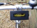
One thing I'd like to try is using one of these with the display fitted inside a clear polycarbonate box. In the past, I've masked off a window very carefully, then spray painted the clear box. When the paint has dried the masking tape can be removed, leaving a clear window for the display. This technique works well, but it's very difficult to get a nice, clean, edge between the paint and the clear window. With one of these bezels the masked area could be larger, so the edge is hidden under the bezel. A smear of clear silicone sealer around the screws would maintain a rain-proof front. The unit in question is my electric bike "fuel gauge" and power switch, which is fitted to the handlebars of my home made electric bike:

Swift display and control.JPG


I can see an order for a few of these on the horizon......................
 

eggdweather

Senior Member
Your display looks really good. I can see the utility of using a Picaxe to handle the motor drive control, some form of throttle control and braking and overrun functions, together with battery voltage display. Watt-Hrs used, range, speed etc.
 

Jeremy Harris

Senior Member
Your display looks really good. I can see the utility of using a Picaxe to handle the motor drive control, some form of throttle control and braking and overrun functions, together with battery voltage display. Watt-Hrs used, range, speed etc.
Thanks for the kind words. It's been working well for some years now, just using the spare pins on the OLED driver 18M2, with the code replacing the original serial driver code. it only turns the power on and off, together with measuring voltage and current to calculate the battery capacity used, as well as display the values and the power being used. There is reset button under the box that resets the capacity on the "fuel gauge" to full when pressed at first power on after changing. The power switch and sensors are tucked away inside the bike speed controller. The membrane push button on the right side of the box turns the power on and off (it has an auto power off function too) but only works when a small magnet is held in the right place to operate a reed switch inside, as a security measure. The schematic is here:

Ebike schematic.JPG

and the code is here for an earlier version that used a smaller battery capacity (the current version is 10 Ah) and where the charge reset switch was incorporated into the charging connector (not a good arrangement, so I changed it to a reset button) :

View attachment 18M2 bike control and display.bas
 

eggdweather

Senior Member
IF bike controls were a common standard, that looks like a useful and desirable after-market add-on that people would want. The stainless steel bezel gives it all weather utility too, laser cut steel is likely to have a nice finish on it to. I found on ebay suppliers who will laser cut SS for a fee, but their prices are much more than buying a ready made bezel from the Picaxe store.
 

Jeremy Harris

Senior Member
That unit just connects in the power lead from the battery pack, so it can turn power on and off and measure the voltage and current being drawn from the battery. It could be fitted to any electric bike, perhaps with some modifications to allow for a different battery voltage or maximum current drawn. I built it primarily to have an indication of how much capacity was left in the battery, like the fuel gauge on a car (it remembers the previous capacity level over a power down), and also to reduce wear and tear on the battery isolating switch. One problem with all electric bikes is that the speed controllers all have large capacitors on the supply line, so there is a very high surge current when power is switched on. This causes mechanical switches to fail, unless they are either massively over-rated or unless a double switch is used, with the first switch position charging the capacitors via a resistor and the second connecting the power directly. The power switch FET in my circuit is deliberately turned on slowly (because of the capacitor across the gate) which reduces the surge current and means that the battery isolating switch only has to carry current, not switch it.
 

Jeremy Harris

Senior Member
Some of these arrived in the post this morning (usual very fast delivery from Rev Ed!). I can confirm that the screw holes line up and the bezel is supplied with M2.5 screws and nuts, together with a paper template for the cut out in the panel. The cut out template is sized so that the metal front of the display just fits into it, then the stainless bezel fits over the top to cover up the black metal bit and just allow the display to show.

They are very nice indeed, and I'm going to try and see if the 16 x 2 version will work on a polycarbonate clear box, as a neater way of finishing off the above display unit.
 

neiltechspec

Senior Member
Thanks for the update.
Could you measure the overall dimensions of the 20X4 plate (and the 16X2 if you have both).

Neil
 
Top