Servo parts

pkf

Member
Hi,

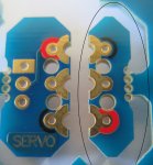
I compared the servo diagram on page 42 of 51 in the bot120 manual (picture 1 as follows):
servo pack from bot120 manual.jpg

with what was in the set (picture 2 as follows) :
possible servo module from set 1.jpg

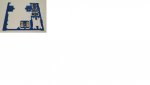
The pictures for the servos are different. Can someone help to confirm that the actual servo module is the one I boxed up with dotted lines in picture 2 ? If yes, where should each of the 2 pieces be attached ?

Thanks.
 

lewisg

Senior Member
I don't know anything about the bot120 but the webpage photo looks a lot like your picture 2. I don't see any servos in this kit. There are 2 motors. You may be confusing the stock motors with the servo upgrade.
 

hippy

Technical Support
Staff member
The main BO120 kit includes a single snap-out servo module interface, as identified on page 6 of the datasheet.

The BOT123 servo pack includes two snap-out servo module interfaces plus an SEF005 interface.

The servo module interfaces, once snapped out, are the same in the BOT120 kit as the BOT123 kit.
 

pkf

Member
Servo circuit boards

Thanks lewsig and hippy, I am aware that there are separate servo parts in the store (perhaps I should have used the title 'servo circuit boards' instead of 'servo parts' earlier).

What I saw on my motherboard was the word "SERVO" marked on one of the small pieces of circuit board, with a small piece of board directly opposite the first small piece. These were the 2 same pieces of small circuit boards I boxed up in picture 2.

My first thoughts were then to :
(a) compare with the bot120 manual (as in picture 1) and I did not find equivalent pieces as in picture 2.
(b) see if there are 2 circuit board pieces for servo (i.e. the 2 pieces I boxed up in picture 2) although the word "SERVO" was only marked on 1 piece.
If yes, then the next question is whether they are supposed to be attached to some part of the motherboard (the design of the pieces are detachable).
If yes, then where on the motherboard may they be attached to and whether additional accessories are needed.
 

hippy

Technical Support
Staff member
From the BOT123 datasheet -

http://www.picaxe.com/docs/bot123.pdf

"The servo modules can be used on any of the motherboard connection positions. However the ‘servo’ command can only be used on the centre rear position B.0 (pulsout commands can be used on any other position).

Therefore it is recommended to normally use the servo in the centre rear position and the SRF005 adapter PCB, connected via the cable, to either of the two outer rear connectors".
 

pkf

Member
My original motherboard came with the accessory parts as shown.
what part 1.jpg
What we mean is connect the part on the left of the image (labelled 'SERVO') to the centre rear position B.0 right ?
If this is the case, please advise how the part on the right should be used. Is this another 'servo accessory circuit board' ?
 

hippy

Technical Support
Staff member
As shown in the diagram on page 6 of the BOT120 manual the module on the right is a "Quarter Module". This forms part of the line tracker assembly as described on page 11.
 
Top