Help with MSGEQ7

Krafter

Member
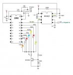
Hey all. I'm working with a picaxe 20m2 and a MSGEQ7 equalizer. I appear to have it doing something and by something I mean it's giving me values on the output but the problem is, it's doing it wether or not I have an audio input. I've checked and rechecked my circuit and all seems good (minus a couple of slightly different resistor values). I've also played with the strobe and reset times but it didn't make a bit of difference. If I comment out the strobe then I get practically nothing out but with it active I get something much higher out. Has anyone played with one of these chips that might be able to give me some tips?

Thanks

Code:
#picaxe 20m2
setfreq m2


symbol ctrlReset    = b.0
symbol ctrlStrobe   = b.1
symbol channelLeft  = c.7

symbol spectrumLeft = b0
symbol position     = b1

position = $1c

low ctrlReset
high ctrlStrobe

main:

high ctrlReset
low ctrlReset
pauseus 38

disconnect
sertxd("Updating.... standby", 13, 10)
reconnect

do while position < 35
	low ctrlStrobe
	pauseus 20
	
	readadc10 channelLeft, spectrumLeft
	poke position, spectrumLeft
	position = position + 1
	
	high ctrlStrobe
	pauseus 20
	'pause 500
	'spectrumLeft = spectrumLeft + 1
loop

high ctrlReset

position = $1c

   do while position < 35
	peek position, b2
	disconnect
	sertxd("The value of b2 at position", " ", #position, " is ", #b2, 13, 10)
	reconnect
	position = position + 1
	'debug
loop

position = $1c

pause 500

goto main

Output without audio input
Code:
Updating.... standby
The value of b2 at position 28 is 68
The value of b2 at position 29 is 83
The value of b2 at position 30 is 73
The value of b2 at position 31 is 142
The value of b2 at position 32 is 71
The value of b2 at position 33 is 204
The value of b2 at position 34 is 199
Output with audio input
Code:
Updating.... standby
The value of b2 at position 28 is 51
The value of b2 at position 29 is 147
The value of b2 at position 30 is 151
The value of b2 at position 31 is 172
The value of b2 at position 32 is 163
The value of b2 at position 33 is 146
The value of b2 at position 34 is 70

IMG_2236.JPG
 

BESQUEUT

Senior Member
What is the
setfreq m2
supposed to do ?
At start up the chip needs to be reset, accomplished by bringing the reset line high and cycling the strobe line.
IMHO : that is not what you are doing...

After the reset line is brought low, the strobe line can then be clocked to retrieve the 7 frequencies sequentially

I do not know what is supposed to be the
pauseus 38
but it is totaly useless because the next sertxd is equivalent to a pause many ms...
 
Last edited:

sghioto

Senior Member
I have breadboarded MSGEQ7 using the below program. The program begins with the proper reset procedure followed by the sequential strobe.

Code:
     pause 100
     let dirsB = %11111111
     high C.0
     high B.0
     low C.0
    
main:let pinsB = %00000010
     let pinsB = %00000011
     let pinsB = %00000100
     let pinsB = %00000101
     let pinsB = %00001000
     let pinsB = %00001001
     let pinsB = %00010000
     let pinsB = %00010001
     let pinsB = %00100000
     let pinsB = %00100001
     let pinsB = %01000000
     let pinsB = %01000001
     let pinsB = %10000000
     let pinsB = %10000001
     goto main
Steve G
 

Attachments

Krafter

Member
What is the
setfreq m2
supposed to do ?
At start up the chip needs to be reset, accomplished by bringing the reset line high and cycling the strobe line.
IMHO : that is not what you are doing...

After the reset line is brought low, the strobe line can then be clocked to retrieve the 7 frequencies sequentially

I do not know what is supposed to be the
pauseus 38
but it is totaly useless because the next sertxd is equivalent to a pause many ms...
@BESQUEUT.

Thank you for the input. I'm not sure what you mean by me not bringing the reset low before cycling through the frequencies. That's the first thing I do in the main sub. The pause I do see that now and agree with you on. Do you mind explaining what you mean a little more or maybe give a suggestion on how you would handle the reset and strobe? And just as an FYI, I found some example Arduino code and did my best at converting it. And the only reason I set the clock speed lower is because the serial output would not display properly in the terminal window. 4800 baud I think.

I have breadboarded MSGEQ7 using the below program. The program begins with the proper reset procedure followed by the sequential strobe.

Code:
     pause 100
     let dirsB = %11111111
     high C.0
     high B.0
     low C.0
    
main:let pinsB = %00000010
     let pinsB = %00000011
     let pinsB = %00000100
     let pinsB = %00000101
     let pinsB = %00001000
     let pinsB = %00001001
     let pinsB = %00010000
     let pinsB = %00010001
     let pinsB = %00100000
     let pinsB = %00100001
     let pinsB = %01000000
     let pinsB = %01000001
     let pinsB = %10000000
     let pinsB = %10000001
     goto main
Steve G
@sghioto

Thank you for the example code. I see what you are doing and I'm a little surprised that you're not using a pause at all. I would take your code and run with it but I want to read the frequencies directly into the picaxe for further analysis. I may even end up using the picaxe as a GPIO for a Raspberry Pi. I'm working on some stage lighting for my band.
 

sghioto

Senior Member
I'm a little surprised that you're not using a pause at all
That's because I was trying to run the sequence as fast as possible.

I want to read the frequencies directly into the picaxe for further analysis
I understand, but this may require using another chip like a 08M to process due to speed limitations.

Steve G
 

Krafter

Member
That's because I was trying to run the sequence as fast as possible.


I understand, but this may require using another chip like a 08M to process due to speed limitations.

Steve G
I have a couple of 08m2s as well as a 20x2. I think I'll use the 20x2 since it's clock speed is up to 64 MHZ.
 

Krafter

Member
I changed out the 20m2 for a 20x2 and I made some good progress. I still get a random numbers with no audio input but when I do have one, I get much higher numbers. I'd like to find a way to zero the analog input with no audio input but if I can't, I think I can still work with it.

Here is some very basic code using HPWM to drive four LEDs. I'm not parsing out the different frequencies when driving the LEDs yet but it still progress.

Code:
#picaxe 20x2
'setfreq m2


symbol ctrlReset    = b.0
symbol ctrlStrobe   = b.1
'symbol channelLeft  = C.3

symbol spectrumLeft = b0
symbol position     = b1

init:
hpwm 0, 0, %1111, 150, 0	; start pwm
position = $1c

low ctrlReset
high ctrlStrobe


main:

high ctrlReset
low ctrlReset
pauseus 38

disconnect
sertxd("Updating.... standby", 13, 10)
reconnect

do while position < 35
	low ctrlStrobe
	'pauseus 20
	
	readadc c.1, spectrumLeft
	poke position, spectrumLeft
	position = position + 1
	
	high ctrlStrobe
	'pauseus 20
	'pause 500
	'spectrumLeft = spectrumLeft + 1
loop

high ctrlReset

position = $1c

   do while position < 35
	peek position, b2
	'disconnect
	'sertxd("The value of b2 at position", " ", #position, " is ", #b2, 13, 10)
	'reconnect
	if b2 > 100 then
		hpwmduty b2
	else
		hpwmduty 0
	endif
	position = position + 1
	'debug
loop

position = $1c

'pause 500

goto main
 

hippy

Technical Support
Staff member
I'd like to find a way to zero the analog input with no audio input
Can you not just tie leg 5 of the MSGEQ7 to 0V or via a low value resistor ?

Each read of the channel levels reduces those levels so you will need to take multiple readings to ensure outputs decay to zero.

In running your 'position' from $1C (26) to 34 (<35) you are actually reading 9 channels. There are only 7, then it restarts from the first. You will possibly be decaying the first two channels faster than the rest. - No $1C is 28 not 26!

I would simplify your code and take advantage of using 'bPtr' and '@bPtr' to put the 7 channel levels in b0 through b6, and also refactor how you are setting your signal levels -

Code:
#picaxe 20x2
#terminal 9600

symbol ctrlReset   = B.0
symbol ctrlStrobe  = B.1
symbol channelLeft = C.1

; b0..b6 used for channel data accessed via bPtr / @bPtr

main:
  gosub ReadChannels
  gosub ShowChannels
  goto main

ReadChannels:
  ;           _                                _
  ; Reset  __| |____________________________ _| |____
  ;          ___   _   _   _   _   _   _   _ ____   _
  ; Strobe _|   |_| |_| |_| !_! !_| |_| |_|      |_|
  ;
  ; ReadAdc      0   1   2   3   4   5   6        0

  high ctrlStrobe
  high ctrlReset
  low  ctrlReset
  for bPtr = 0 to 6
    low  ctrlStrobe
    readadc channelLeft, @bPtr
    high ctrlStrobe
  next
  return

ShowChannels:
  for bPtr = 0 to 6
    sertxd( "Channel ", #bPtr, " value ", #@bPtr, CR, LF )
  next
  sertxd( CR, LF )
  return
 
Last edited:

Krafter

Member
Can you not just tie leg 5 of the MSGEQ7 to 0V or via a low value resistor ?
I tried that with some higher resistance resistors last night (10- 20k) and it didn't make a difference. I just dug out some lower resistance resistors from 22 ohm to 5k. I settled on a 2.7k as it seems to give the best results. I think I'll end up using a pot to try and find the best value.

Each read of the channel levels reduces those levels so you will need to take multiple readings to ensure outputs decay to zero.

In running your 'position' from $1C (26) to 34 (<35) you are actually reading 9 channels. There are only 7, then it restarts from the first. You will possibly be decaying the first two channels faster than the rest. - No $1C is 28 not 26!
I would simplify your code and take advantage of using 'bPtr' and '@bPtr' to put the 7 channel levels in b0 through b6, and also refactor how you are setting your signal levels -
Define "setting". As in the gain? Right now, I'm just using the volume control on my phone playing music playing directly into the circuit but I do have a 20K resistor protecting the MSGEQ7. I will eventually build a pre-amp for a small microphone that will be used to operate the lights. If you mean analyzing the 7 different frequencies, I haven't gotten that far yet.:p

Code:
#picaxe 20x2
#terminal 9600

symbol ctrlReset   = B.0
symbol ctrlStrobe  = B.1
symbol channelLeft = C.1

; b0..b6 used for channel data accessed via bPtr / @bPtr

main:
  gosub ReadChannels
  gosub ShowChannels
  goto main

ReadChannels:
  ;           _                                _
  ; Reset  __| |____________________________ _| |____
  ;          ___   _   _   _   _   _   _   _ ____   _
  ; Strobe _|   |_| |_| |_| !_! !_| |_| |_|      |_|
  ;
  ; ReadAdc      0   1   2   3   4   5   6        0

  high ctrlStrobe
  high ctrlReset
  low  ctrlReset
  for bPtr = 0 to 6
    low  ctrlStrobe
    readadc channelLeft, @bPtr
    high ctrlStrobe
  next
  return

ShowChannels:
  for bPtr = 0 to 6
    sertxd( "Channel ", #bPtr, " value ", #@bPtr, CR, LF )
  next
  sertxd( CR, LF )
  return
Thanks for the example code. You taught me a new command that I didn't know existed and it works well in the application.

PS
I know my newbyness is showing in this thread in both my coding and electronic experience and I really appreciate the help that I'm getting. Believe it or not but I am a programmer. Just not structured text such as this. More ladder logic than anything. I also work with high end analog, digital and communication devices everyday. I just do this stuff as a hobby.
 
Top