I wonder if others think this would be a useful improvement to the usefulness of manual2...
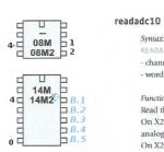
Instead of just showing images of the various picaxe chips at the left of each Basic Command, place a (port.)number next to each pin that can be used with the command that corresponds with the pin part of that command.
For example, if the count command can use an input pin, those pins would have numbers and the others would be blank; if the command assumes the use of a particular pin or pins (e.g. hi2cout) put some label (e.g. a tick or "sda") next to those pins.
This would help in several ways: it save time looking up another manual to see which pin is which, it avoids silly mistakes due to the 2-stage lookup process because those pins are clearly marked next to the command, and it may reduce problems of ambiguity (pin number/leg number/ADC channel can be all different, and X2 conventions are different to the rest), and in some cases the command might say it works with "an input pin" but some people might wonder if that includes (say) a serial input pin.
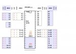
One possible problem I can see with this is that the largest two chips, the 28 and 40 pin picaxes, would either need to be shown separately (taking more vertical space on the page) or have multiple columns of labels beside the pins, taking extra space horizontally... although even for one of the more complicated examples of combining 28x and 40x parts in one diagram (example picture attached, perhaps fancier than it needs to be) it isn't too bad, I think. I used different colours for X2, X1, etc types in my test example, but colour is not essential ... a B&W copy is still okay.
Without trying to combine different sized chips, the diagrams can be simpler, and about as small as they are now, of course.
Another approach would be to take one chip, say a 20M2 and make a big, clear poster with columns beside each pin for each type of main command (e.g. readadc10, input/pulsin, pwmout, etc)... not sure if I saw something a bit like that already somewhere.
What do others think?
Instead of just showing images of the various picaxe chips at the left of each Basic Command, place a (port.)number next to each pin that can be used with the command that corresponds with the pin part of that command.
For example, if the count command can use an input pin, those pins would have numbers and the others would be blank; if the command assumes the use of a particular pin or pins (e.g. hi2cout) put some label (e.g. a tick or "sda") next to those pins.
This would help in several ways: it save time looking up another manual to see which pin is which, it avoids silly mistakes due to the 2-stage lookup process because those pins are clearly marked next to the command, and it may reduce problems of ambiguity (pin number/leg number/ADC channel can be all different, and X2 conventions are different to the rest), and in some cases the command might say it works with "an input pin" but some people might wonder if that includes (say) a serial input pin.
One possible problem I can see with this is that the largest two chips, the 28 and 40 pin picaxes, would either need to be shown separately (taking more vertical space on the page) or have multiple columns of labels beside the pins, taking extra space horizontally... although even for one of the more complicated examples of combining 28x and 40x parts in one diagram (example picture attached, perhaps fancier than it needs to be) it isn't too bad, I think. I used different colours for X2, X1, etc types in my test example, but colour is not essential ... a B&W copy is still okay.
Without trying to combine different sized chips, the diagrams can be simpler, and about as small as they are now, of course.
Another approach would be to take one chip, say a 20M2 and make a big, clear poster with columns beside each pin for each type of main command (e.g. readadc10, input/pulsin, pwmout, etc)... not sure if I saw something a bit like that already somewhere.
What do others think?
Attachments
-
 70.1 KB Views: 43