two 18v battery's in parallel

newplumber

Senior Member
Hello to everyone and yes even you
I was going to build another remote led sign that after computing all the power usage and testing
I came up with 310 mill amps on the 18 volt side
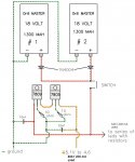
and no more then 100 mill amps on the 5 volts side which would run the picaxe and mosfets but to add just in case I added on my schematic 400 mA for 18 volt and 200 for 5v mA
Since this plan does work (from me testing only 1 battery) and nothing is heating up , everythings cold, my question is can I have those diodes on the positive side because I am going to recharge those batterys
one at a time and will it stop the batterys from heating up trying to equalize? (which i have not yet tried)
Example is if you have one battery 90% charged and one 40% charged in my theory without silicone diodes the 90% would rush into the 40% to equal which may cause overheating
I know my schematic is not right because i designed it ,but with two power regulators I was hoping it helps keep them cool
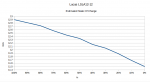
The reason why I put resistors on the middle pins is because at 18 volts (which is the highest these batterys can charge) it gives me 5.1 volts on the L7805
and when the batterys are drawn down to about 8.5 volts the L7805 reads about 4.8 volts so I was trying to keep the voltage as close to 5 no matter what the batterys voltage is
I know the picaxe 20m2 can run down to <3v
I can easily redo this schematic with a better plan if anyone has any thought
Thanks again forums "if this thread isn't proper for forums then sorry delete thread"
Your last friend on the list
 

Attachments

premelec

Senior Member
Hi - you might [or might not!] want to look into using switching buck converter to regulate your 5volt supply rather than dissipating a bunch of energy in the two 3 pin regulators... Ordinarily two identical batteries could be paralleled without isolation - no diodes... and if you use diodes use low drop schottkey types to save power loss. If your batteries are charged differently for some reason then the diodes are necessary... And note that only the higher voltage battery will have current drawn until it gets to the lesser battery voltage...
 

inglewoodpete

Senior Member
The diodes are essential the protect the batteries from trying to charge/discharge each other. Batteries are never identical: the fact that you have one now and getting another means that they will both be in different parts of their life cycles. I would use schottky diodes (Eg 1N5819 (1 amp) or 1N5822 (3 amp)) as they have a lower forward voltage drop - less wastage.

I'm not sure what you are supplying with the 5-volt circuit but 5.1 volts will be perfectly safe for most components. The two cascaded 78xx regulators with stop regulating properly with an input of around 11.5 volts.

I would steer away from 78xx-type regulators for a battery operated circuit due to the quiescent current wastage and also the wastage due to the 13 volt drop across them (resulting in an efficiency of around 20%). Consider a switch mode voltage regulator module, which can have an efficiency around 90% or better.

Also, you don't mention what technology the batteries are. Running any battery down to 40% of their rated voltage is not good for them. If the batteries are lithium-based (or lead-acid), it could be fatal for them.
 

SteveDee

Senior Member
I suggest you use a 78B5.0 (5V/1A) instead of a linear regulator. The input range is 6.5V - 32V and they run cool. I must have 8 or 9 of these running in RaspberryPi/Picaxe projects, and never had any problems: http://www.recom-power.com/pdf/Innoline/R-78Bxx-1.0_L.pdf

If your plan is to pull out one battery and charge while the display continues to run on the other, then I'd suggest you make a more sophisticated power controller circuit.
e.g. monitor each battery using Picaxe ADC, run from one until charge drops below threshold, switch to second and operate "charge #1" indicator. That will give you best use of 2 batteries with [near] continuous use.
Obviously with your initial circuit, both batteries just get drained until they are both flat.

For battery discharge (state of charge) and when to recharge, you need to look at the battery manufacturers information (which can be difficult to track down). For the Lucas batteries that I use in my birdbox camera systems, its OK to run down to 40%. In fact I push them a bit harder, and the Picaxe does not stop the system running until the voltage drops below 12V.

Blocking diodes; again you need to look at the manufacturers data. Many people assume that silicon diodes have a forward voltage drop of approx 0.65V. The actual drop depends upon the diode, the temperature and the forward current. e.g. a 1N4000 series diode at 25'C with forward current of 200mA has a voltage drop >800mV. I'm not sure that really matters in your case, you just want protection.

I hope some of this helps.
 

Attachments

fernando_g

Senior Member
I second the suggestion to use a switchmode regulator instead of a linear one. There are many vendors offering them, in 3-pin packages that are drop-in replacements to common 7805 regulators.

Also, Steve's suggestion to use a Picaxe to control the power flow of the two batteries. This can be a pair of P-channel mosfets, which also serve as oring diodes with far less losses.

As part of the intelligent control system, you can also have a disable circuit to prevents a battery from over discharging (very important on lead-acid batteries), a low battery alarm, and any other bells and whistles you can think of.
 

newplumber

Senior Member
Thanks for all your input

I went back to drawing board and redrew my Schematic
I am using only 34mA on the 5 volt side because i forgot I had leds attached which will be deleted
I have some buck converters which I probably will use but looking at the recom 78b5.0 is a cool idea
I will try to use schottky diodes
When I build this sign I will list it on finished projects or (finished burnt projects)
Thanks again for your info thats why I ask the pros

Your slow understanding friend
 

techElder

Well-known member
Sorry, newplumber, not trying to be negative, but I don't understand creating a new design using "NICAD" batteries. Do you just have these laying around and are trying to build the unit around them?

NICADs are really finicky. That is why you don't find many (if any) portable equipment using them anymore.
 

newplumber

Senior Member
Sorry, newplumber, not trying to be negative, but I don't understand creating a new design using "NICAD" batteries. Do you just have these laying around and are trying to build the unit around them?

NICADs are really finicky. That is why you don't find many (if any) portable equipment using them anymore.
LOL you can be negative Texas and rip on my harbor freight schematic jk i know you wouldn't but yes I bought a bunch of these cheap harbor freight drills with these batterys so I figured I would use them up in my sign since they either go into the garbage or burn up in my sign (thats why its portable) If you charge them and try to use
them with the cordless drills you might get 1000 rotations before the batterys go dead. So in short i am detouring the battery's path to the trash. After they fail I will probably redesign and use better ones
 

inglewoodpete

Senior Member
..... If you charge them and try to use them with the cordless drills you might get 1000 rotations before the batterys go dead. So in short i am detouring the battery's path to the trash.
If that is the case, you definitely need those blocking diodes. Personally, I would not waste much time designing something so close to the trash can.
 

newplumber

Senior Member
Thanks inglewoodpete yes i will put those schottky diodes you mentioned on.. when I'm done building it I will try to do a simple schematic and info on the batterys like how long they hold up etc.
I figure its funner to experiment and learn how not to do something then to just do nothing, of course my pile of how not to experiments is adding up
 

friis

Senior Member
Hi SteveDee,
I have a solar panel supplying two 3.7v rechargeable batteries giving 7.4 V
output which I was planning to use to run a PICAXE 14M2. Would the R-78B5.0-1.0
be suitable to reduce from 7.4 v to 5 v? Or is there something more suitable?
I have looked a different step-down converters but I have trouble understanding
the specifcations.
best regards
torben
 

BESQUEUT

Senior Member
A 7805 will waste 2,4 V, so efficiency is 5/7.4=67%
a step down regulator efficiency is claimed to be max 96%
but maybe something between 80 to 90%.
So it's a little better in your case.
It's more interesting if power supply is 12 or more volts.
 

SteveDee

Senior Member
...Would the R-78B5.0-1.0 be suitable to reduce from 7.4 v to 5 v? Or is there something more suitable?...
We probably need a full circuit of your idea.

First, on the solar side, do you have a good (and safe) match between solar panel and the 2 batteries, which I assume are Lithium and I assume are in series?

Second, how much current will your Picaxe circuit draw from a 5V supply?

The thing about linear voltage regulators is they act like a variable resistor [OK, that is a huge simplification]. If your 5V circuit draws (say) 500mA, then the power in the circuit is:-
P = VI = 5V x 0.5A = 2.5W

...and if the input to the regulator is 7.4V, the power dissipated in the regulator is:-
P = VI = (7.4V - 5V) x 0.5A = 1.2W

Depending upon the rating of your solar cells and batteries, that may be a huge amount of power to waste, or it may be insignificant. Either way, your system is consuming 3.7W but only putting 2.5W to good use. (also your regulator may need a heatsink).

Do the calculations again for 10mA, and the wasted power is only 0.012W (or 12mW).

If you take a look at the full circuit of my bird box system (http://captainbodgit.blogspot.co.uk/2015/12/birdbox2016-role-of-picaxe.html) you will notice that I use a simple linear regulator for the Picaxe (78L05) and a switching regulator for the RaspberryPi (78B5). In the first case the power loss doesn't bother me, but for the Pi it certainly would. A switching regulator is only going to 'waste' a very small percentage of the total power.

When you look at the data sheets, take special notice of the maximum and minimum input voltage. I think 7V is minimum for a 7805, and 6.5V for the 78B5. Also note the max current, and whether the device will need a heatsink to dissipate any heat.

Is the 78B5 the best device to use? I don't know, as I don't know what else is available.

The 78B5 is a hybrid, so components have been built onto a small board and then potted in a plastic potting box. This makes the device quite expensive, but it seems to be a quality product.

I hope this is of some help to you.
 

premelec

Senior Member
The switching regulators ref'd by BESQUEUT work well and are certainly inexpensive... a possible downside to switching regulators is high frequency electromagnetic noise - not a problem in many applications...
 

friis

Senior Member
Hi everybody,
The solar panel I bought is one made for supplying a camera - to be used to
taking pictures of wild life, I think. I bought it because I understood it
would deliver 6 V and because it is a nice package with mounting bracket,
batteries etc.
I have been unable to find out how much power the PICAXE 14M2 draws, but I
assumed it would be about the same as a camera. Anyway, the picaxe only really
works briefly at the most every 1/4 of an hour - like a camera - the rest of
the time it sleeps. Maybe I can run two PICAXEs of one solar panel.
I have ordered 1 (set of 10) of the type proposed by BESQUET and I am going to
use that - unless somebody advices me otherwise.
torben
 

SteveDee

Senior Member
...The solar panel I bought is one made for supplying a camera - to be used to
taking pictures of wild life...
I would be interested in a link to the solar panel you are using.

A few more ramblings.

Assuming the solar panel did not come with batteries, then since your solar panel is rated at 6V, I think you you should match that with 4 x 1.2V rechargable MiMH batteries ("AA" or "AAA" size). Just feed the solar panel output via a silicon diode to the batteries. Note that a 1N4000 series diode has a variable voltage drop, e.g. it is lower at high currents/higher temperatures {maybe 0.7V} and higher at lower currents/lower temperatures {maybe 0.8V}.

Caution: The max supply voltage for a 14M2 is 5.5V, which is much higher than 4 NiMH batteries, but you need to make sure the battery terminal voltage (fed via a diode) does not exceed 5.5V with the solar cell in full sunshine (in June).

***Alternatively the component specified by BESQUET looks excellent. Its cheap, and it works down to 4.75V.

Picaxe current draw is very low. On my bird box system it is just 3mA for an 08M2, plus 8mA for the attached components (mainly a photo diode and transistor). So in your case you need to assess your 14M2 circuit (e.g. is it driving relays, or other 'juicy' components?). From what you have said, it just fires a camera every 15mins. However, is the camera also powered from the same 6V supply? (I guess it is). If so, what does that draw?

If the solar panel came with the camera we must assume it is powerful enough. So the question is; is it powerful enough to run the equipment AND charge your battery during the day to a level which will maintain power through the night?
 

friis

Senior Member
Hi Stevedee,
Here is the address:

https://mail.google.com/mail/u/0/?tab=wm#search/jagt+jakt/1548a3e34ee290ec

The name of the product is there.

The address of the supplyer is:

http://jagt-jakt.dk/

The solar panel comes complete with batteries.

I was glad to see the power consumption of the PICAXE - I hav'nt seen that
before. The 14M2 just sends a signal to a central PICAXE which does the
work and is powered by the mains. So every 1/4 hour (or 1 or 1/2 hour or
5 hours) it receives a signal telling it the check the humidity and report the
result back. I assume that takes very little power.
torben
 

lbenson

Senior Member
So every 1/4 hour (or 1 or 1/2 hour or 5 hours) it receives a signal telling it the check the humidity and report the result back. I assume that takes very little power.
torben
Wirelessly listening continually for a signal to report back would take a considerable amount of power, depending on what wireless you use. Much less would be consumed if the remote device just reported significant changes.
 

friis

Senior Member
Hi Ibenson,
In the periods in between receiving requests from the central system the
decentral PICAXEs are sleeping.
torben
 
Top