PhilHornby
Senior Member
A while ago, I purchased a Wireless Thermometer system from Imagintronix and realised that the add-on sensors would make cost-effective temperature sensors for other projects.
See: http://www.imagintronix.co.uk/buy/wireless-thermometer-sensor-extra-sensor-for-xh200-xh210_12.htm (They seem a little confused about the Part number - only one of mine is marked, and it says "XT200".)
At the time of writing, they are less than £6 each - which is cheaper than building your own!
They transmit temperature readings using 433MHz RF and send a data packet (repeated twice) at approximately 55 second intervals. My initial research lead me to this internet posting: https://github.com/merbanan/rtl_433/issues/25 - which contains enough information to use them - though the CRC-checking hadn't been fully understood at that point.
I used this software http://reveng.sourceforge.net/ to analyse the CRC (In a nutshell, it compares two sets of two data samples - and the result they have in common is probably the correct algorithm.)
I then used this (Python) program https://pycrc.org/ to generate code to implement that CRC. (Unfortunately, it produces 'C' code, but I managed to translate it into Picaxe Basic without having to understand exactly how it works )
)
Packet structure :-
; A "0" time period is approx. 550 uS and "1" is approx. 1.465 mS. Each bit is separated by 976uS of 'space'.
;
;
;
;
; The entire packet is only sent twice by the XT200, separated by 40mS. It repeats once every 55 seconds - and the IM200 wakes for ~ 1.5 secs
; to receive it.
;
; The formula for calculating the 10bit Temperature Code (TC) is:
;
; TC = (623 - (10 x C)) - Where C is the temperature in the range -40.0c to +62.3c
;
; When C is negative, the two minuses combine as a plus.
;
; e.g.
;
; TC = 623 - 623 => 0 ;+62.3c
; TC = 623 - 0 => 623 ;0c
; TC = 623 + 400 => 1023 ;-40.0c ( two minuses = plus)
;-
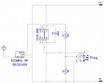
NOTE: Since I first uploaded this code, I have moved the project off the breadboard and into an environment more representative of a real-world deployment. It immediately became clear that a high quality 433MHz RF receiver is required. The best one I have found so far is the "WL101-341 Superhet receiver". The RXN3-S (also superhet) came a close second. The cheaper receiver modules (the ones with adjustable cores, rather than a SAW) have great difficulty locking on to the XT200 signal, presumably because the preamble is only 8 bits. The WL101-341 (which was only £2.50 on eBay) gives far greater range than whatever Imagintronix used in their own receiver module.
I have updated some of the timing values in my code to be more forgiving of distortions in the signal.
Minimal circuit to implement this code:-
See: http://www.imagintronix.co.uk/buy/wireless-thermometer-sensor-extra-sensor-for-xh200-xh210_12.htm (They seem a little confused about the Part number - only one of mine is marked, and it says "XT200".)
At the time of writing, they are less than £6 each - which is cheaper than building your own!
They transmit temperature readings using 433MHz RF and send a data packet (repeated twice) at approximately 55 second intervals. My initial research lead me to this internet posting: https://github.com/merbanan/rtl_433/issues/25 - which contains enough information to use them - though the CRC-checking hadn't been fully understood at that point.
I used this software http://reveng.sourceforge.net/ to analyse the CRC (In a nutshell, it compares two sets of two data samples - and the result they have in common is probably the correct algorithm.)
I then used this (Python) program https://pycrc.org/ to generate code to implement that CRC. (Unfortunately, it produces 'C' code, but I managed to translate it into Picaxe Basic without having to understand exactly how it works
)Packet structure :-
; A "0" time period is approx. 550 uS and "1" is approx. 1.465 mS. Each bit is separated by 976uS of 'space'.
;
;
Code:
; +--------+
; |00000000|  The first 8 bits are only to train the AGC in the IM200 receiver. (Their contents are not critical; other bits work too)
; +--------+
; |110011tt|  "110011" is what the IM200 uses to identify the packet. The next 2 bits in this byte, are the top two bits of the 10bit
; +--------+  temperature reading. i.e. Msb first bits 9->8
; |tttttttt|  Next 8 bits of temperature reading. bits 7->0
; +--------+
; |ssssssss|  An arbitrary 8bit value used to identify the sensor. Generated randomly when batteries are inserted.
; +--------+
; |00000000|  Possibly used in other models, or maybe it's just the sensor 'type'. Always = 0 from XT200 sensor. If this byte is non-zero,
; +--------+  the IM200 display unit will NOT accept the temperature reading.
; |cccccccc|  8 bit CRC. (of Preamble, Temperature, SensorId and the zero byte)
; +--------+  CRC is described by "reveng" as: "width=8 poly=0x31 init=0x99 refin=false refout=false xorout=0x00 check=0xd5 name=(none)"
;
; The entire packet is only sent twice by the XT200, separated by 40mS. It repeats once every 55 seconds - and the IM200 wakes for ~ 1.5 secs
; to receive it.
;
; The formula for calculating the 10bit Temperature Code (TC) is:
;
; TC = (623 - (10 x C)) - Where C is the temperature in the range -40.0c to +62.3c
;
; When C is negative, the two minuses combine as a plus.
;
; e.g.
;
; TC = 623 - 623 => 0 ;+62.3c
; TC = 623 - 0 => 623 ;0c
; TC = 623 + 400 => 1023 ;-40.0c ( two minuses = plus)
;-
NOTE: Since I first uploaded this code, I have moved the project off the breadboard and into an environment more representative of a real-world deployment. It immediately became clear that a high quality 433MHz RF receiver is required. The best one I have found so far is the "WL101-341 Superhet receiver". The RXN3-S (also superhet) came a close second. The cheaper receiver modules (the ones with adjustable cores, rather than a SAW) have great difficulty locking on to the XT200 signal, presumably because the preamble is only 8 bits. The WL101-341 (which was only £2.50 on eBay) gives far greater range than whatever Imagintronix used in their own receiver module.
I have updated some of the timing values in my code to be more forgiving of distortions in the signal.
Minimal circuit to implement this code:-
Attachments
-
18.9 KB Views: 11
Last edited: