Totally misunderstanding OpAmps, I guess...

edmunds

Senior Member
Dear all,

I have been able to avoid the confusing topic of OpAmps for years. Now I thought it was time to get the confusion out of the way and my linear ccd sensor signal seems to be the right thing to play with.

If you recall from other threads, I was able to achieve about 0.2V output difference between black and white surface signals with good repeatability. I believe it would not be so wrong to call this amplitude for our case. As some of you have noted, this is not much and increasing the amplitude would be desirable. I have not been able to achieve this with extra lighting, clock speeds and integration time in the span available with picaxe. While I have a solution that works anyway with internal comparator in a constant light situation, almost non existent hysteresis allowance means that it requires a lot of calibration to be accurate in changing ambient lighting, which is not trivial if not impossible to do flawlessly.

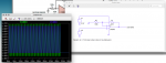
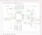
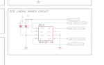
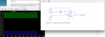
So, I read up a little bit and what I read on the internet seemed to confirm my idea that an OpAmp can help to increase the amplitude of such signal. I set up a circuit in LTSpice to my best understanding, but all I can achieve is a gain of approx 1.5x. While this is an improvement, it is hardly worth the extra PCB space. Some images attached. What am I doing wrong? Or otherwise - where are the hundreds of times of gain possibility? :)

Screen Shot 2016-05-10 at 00.50.18.png

Thank you all for your time,

Edmunds
P.S. Blue is the input signal at "+" of the OpAmp, green is the amplified (and shifted) signal.
 

BeanieBots

Moderator
A gain of ~1.5 for the resistor values you have is about right.
If you want higher gain, reduce R2 and/or increase R1. When R2=R1, the gain will be 2.
I don't know that particular op-amp but do you have the correct supply rails. Does it require dual rail and can it swing close to the rails.
With op-amps that struggle to get close to 0v (when no negative rail is available) simply putting a 1k load on the output helps a lot.
There are other (better) methods of improving performance but let's get the basics right first.
There's loads of example circuits out there but this might help for the specific configuration you are after.
http://www.electronics-tutorials.ws/opamp/opamp_3.html

EDIT: Just had quick browse and found this. http://www.ti.com/lit/an/snoa621c/snoa621c.pdf
It's quite a nice list of basic examples in a downloadable pdf format.
 
Last edited:

Reloadron

Senior Member
As drawn I believe the gain would be R1 / R2 so R1 & R2 should be reversed. As drawn your gain would be 0.6 which can't happen. Reversing R1 and R2 as drawn will give you a gain of about 1.66. This is your operational amplifier and note the typical application on page 1. The gain would be 10M / 100K or 10. The choice of operational amp is good as it is a rail to rail amp and allows a single supply. Anyway, that is the problem I see with your drawing.

Ron
 

cravenhaven

Senior Member
I always have trouble remembering the formulas so I work it through from ohms law (at least I can remember that :)). In your example:
1. Lets assume the output is at 1 volt, therefore there is a current of 1/(120k+72k) = 5.2 uA through the resistors because the opamp can be considered perfect and consumes no current at its inputs.
2. With the current flowing as above, you end up with a voltage of 120k *5.2/1,000,000 = 0.625 (v=i*r) at the junction of the resistors which is the (-) input to the opamp.
3. The + and - inputs to an opamp are always at the same voltage (unless badly overdriven) so therefore the gain can be calculated as output voltage/input voltage = 1/.625 = 1.6.
 

edmunds

Senior Member
Thank you for all the responses.

However, this is what I get with 10M and 100k values - hardly any amplification at all :)

Screen Shot 2016-05-10 at 19.08.58.png


Thank you for your time,

Edmunds
 

tmfkam

Senior Member
Assuming you were amplifying a 1.5V signal by 10, wouldn't you need a power supply of at least 15V not 3.3V? Or am I misunderstanding Op-Amps too?
 

AllyCat

Senior Member
Hi

What frequency are you simulating? The "gain-bandwidth product" doesn't seem to be quoted in the LT6003 data sheet, but normally would be expected to be at least 1 MHz, even for a 1 kHz signal. But the data sheet does quote a "full-power bandwidth" of 170 Hz, which suggests it's only intened for dc/low-frequency applications. Try simulating a more "normal" Op-Amp.

Strictly, 10m Ohm is ten milli Ohms not Mega Ohms, but perhaps the simulator doesn't know or care! And unless you (can) specify the supply voltage it probably doesn't bother about simulating any "output voltage overload".

EDIT: Looking at the data sheet in more detail, the (maximum) typical output slew rate is 1 volt/ms (equivalent to 150 mV rms of 1 kHz sine wave) and the gain-bandwidth product (graph) about 2 kHz (tested at 100 Hz), i.e. a maximum (open loop) gain of 2 at 1 kHz.

Cheers, Alan.
 
Last edited:

hippy

Technical Support
Staff member
I'm no expert on analogue circuitry but I have used op-amps and they have worked to increase signals as expected and predicted, though I have forgotten the equations.

I am wondering if there is something odd going on in the simulation. Perhaps choose lower resistance values to rule out internal calculation issues, use the same resistances for Rfeedback and Rground and perhaps start with a 741 op-amp in case it's something peculiar with the type you have chosen, and bump the rail voltage up to something higher as tmfkam suggests.
 

edmunds

Senior Member
EDIT: Looking at the data sheet in more detail, the (maximum) typical output slew rate is 1 volt/ms (equivalent to 150 mV rms of 1 kHz sine wave) and the gain-bandwidth product (graph) about 2 kHz (tested at 100 Hz), i.e. a maximum (open loop) gain of 2 at 1 kHz.

Cheers, Alan.
Dear Alan,

This must be it then :). Because I did try all other options from the suggestions above. I will see if I can find an OpAmp with better slew rate that is also available in the simulator and some tiny package.


Thank you and best regards,

Edmunds
 

AllyCat

Senior Member
Hi,

Yes, the Op-Amp formulae assume that the gain and/or bandwidth is "infinite" (i.e. very large) compared with the value(s) actually required. Thus even a simple "audio" application may need an Op-Amp with a G-B product well into the MHz or even GHz region. So Op-Amps tend to be used for "convenience" rather than (power) efficiency.

IMHO, probably the best way to save space is not to add an Op-Amp. ;) I'm not clear what you want to achieve: Just to create a logic level at an accurate "decision" level, or to convert the 200 mV range into an analogue value? But a raw PIC(axe) should be able to do either:

Most PICaxes have an internal "DAC" (bias chain) and a comparator, that can be set to detect any threshold voltage within about 100 mV. This could be reduced further using an external component or two (resistor, diode, etc.).

Whilst it is discouraged, the 1 volt FVR may be used as the ADC reference, so a 200mV amplitude signal can almost span a full byte using READAC10.

Cheers, Alan.
 

inglewoodpete

Senior Member
My op-amp of choice, when working with PICs (including PICAXES) is the Microchip MCP6021 (single) and MCP6022 (dual). These are rail-to-rail 5v devices with a bandwidth (GBWP) of 10MHz - well suited to interfacing to a PICAXE.

A bonus when using the MCP6021 is the Vref pin which is a simple, resistive mid-supply voltage reference - so valuable when one of the op-amp's supply rails is 0v.

I would shy away from the 741 when working with microcontrollers because of the need for higher voltage + and - rails. The output of older op-amps like the 741 cannot swing within about 2 volts of their supply pins, so cannot effectively be run from a 5 volt supply.
 

Flenser

Senior Member
alleycat has spotted your issue.

10M is not 10 megohm in LTspice, it is 10 milliohm. To specify 10 megohm in LTspice you need to use the "Meg" qualifier. i.e. Try "10Meg" for your R1.
 

Reloadron

Senior Member
OK, I may have this all wrong but it looks like you have an optical sensor to detect Black and White, as used in a robotic device to follow a line or whatever you choose. You have outputs of 1.5 and 1.7 volts so there is a 200 mV spread between the two colors. Would that be correct? So really all you are concerned with is that 200 mV difference which tells you where your sensor is (over black or over white). The 1.5 volts serves no real purpose. Now if that is correct I would consider the use of a rail to rail operational amplifier suitable for low voltage applications and configure it as a differential (difference) amplifier. This way you take the 200 mV, reference it to 0 (zero) and amplify it.

Here is a basic example of what I am getting at:


If you look at the data sheet for the chip I used it can be found here. See 9.2.2 for an example of a differential amplifier section. The attached drawing I offset the 1.5 volts and amplify the difference. A LMV324 could be used (4 EA LMV321 on a single package) and configured as an instrumentation amplifier as seen paragraph 9.2.3.1. Would something like that Vin and Vout be of any help? Also my Vout is inverted but if you only care about black or white it should not matter.

Ron
 

edmunds

Senior Member
Dear all,

Thank you for your responses, I have managed to sort out the OpAmp situation in LTSpice. There were two main problems - one was the OpAmp was too slow and the other one was to reference to ground was the best way. Now I do have what I wanted in a simulator.

This is, however not possible with the smallest of OpAmps and requires a bunch of resistors and even a few caps to be totally honest.

Not good.

Edmunds
 

edmunds

Senior Member
OK, I may have this all wrong but it looks like you have an optical sensor to detect Black and White, as used in a robotic device to follow a line or whatever you choose.
Ron
Dear Ron,

On the contrary - you have it all right :). Thank you for your input!

Edmunds
 

edmunds

Senior Member
Hi,

IMHO, probably the best way to save space is not to add an Op-Amp. ;) I'm not clear what you want to achieve: Just to create a logic level at an accurate "decision" level, or to convert the 200 mV range into an analogue value? But a raw PIC(axe) should be able to do either:

Most PICaxes have an internal "DAC" (bias chain) and a comparator, that can be set to detect any threshold voltage within about 100 mV. This could be reduced further using an external component or two (resistor, diode, etc.).

Whilst it is discouraged, the 1 volt FVR may be used as the ADC reference, so a 200mV amplitude signal can almost span a full byte using READAC10.

Cheers, Alan.
Dear Alan,

I am trying to "create a logic level at an accurate "decision" level". Please find the relevant pieces of schematics below. I am running the sensor with SPI interface. I.e. the SPI clock pin connected to the clock input of the sensor and video output of the sensor read by SHIFTIN command. While I can get it to read in zeros and ones if I carefully position the sensor in the way it gets the right amount of light so the high/low threshold would be right where it needs to be, this is, of course, not practical. So I fed the video line into the comparator, SFRed the comparator to output the signal on a pin and connected it back to another pin, which I will try to read with SHIFTIN.

The reference for the comparator has to be dynamic, because my 200mV amplitude is walking up and down the voltage scale depending on ambient lighting. So I was thinking I could READADC the one shot of video (64 pixels), average it and adjust the reference based on that.

Now I look at reference options and the least components is using "internal resistor ladder". If I read and remember both, picaxe manual and pic datasheet correctly, we have 24 positions for 40X2. At 2.8V supply, this gives us about 0.12mV per step. While in theory sufficient, this is very little to play with and thus I was looking if I can make this more robust, sort of.

I still have not had time to put all of this together and test properly as it requires me to adjust my I2C display driver, since the SerOut pin is now a comparator output and I cannot see a thing of what is going on. But I will get to this one day and will report back, if it works and especially if it does not :).


Regards,

Edmunds

Screen Shot 2016-05-27 at 14.38.00.pngScreen Shot 2016-05-27 at 14.38.15.png
 

hippy

Technical Support
Staff member
Does the video signal have to be read using SPI or can you clock it slower and use READADC to grab each pixel level ?

I think it would be worth trying that as the differences between light and dark should be distinguishable even at 5V ADC Vref with 8-bit samples. Read 64 samples into 'ptr' or 'bptr'' storage, calculate the average of those, and then simply compare if values are higher or lower, or something like that.
 

edmunds

Senior Member
Does the video signal have to be read using SPI or can you clock it slower and use READADC to grab each pixel level ?

I think it would be worth trying that as the differences between light and dark should be distinguishable even at 5V ADC Vref with 8-bit samples. Read 64 samples into 'ptr' or 'bptr'' storage, calculate the average of those, and then simply compare if values are higher or lower, or something like that.

Hippy, thank you for your response.

I have not managed to get "slower than SPI" working, because I get too much exposure, i.e. the sensor gets saturated during the minimum number of pulses required for integration. I have been considering adding a pinhole camera - a box with a small hole. If I can get the box right with small enough hole and thin enough walls, then it might keep the surplus light out. If it helps or not with amplitude is a good question and I guess remains to be seen. This requires even more time which I have not found at this point. But, true, this is another direction to investigate.

Edmunds
 
Last edited:

hippy

Technical Support
Staff member
I have not managed to get "slower than SPI" working, because I get too much exposure, i.e. the sensor gets saturated during the minimum number of pulses required for integration.
Not sure how the device actually works but, if it is sample then churn out, would it be possible to SPI the fast initial integration pulses, then switch to bit-banging pulses and READADC at a slower rate ?
 

edmunds

Senior Member
Not sure how the device actually works but, if it is sample then churn out, would it be possible to SPI the fast initial integration pulses, then switch to bit-banging pulses and READADC at a slower rate ?

A very interesting suggestion :). Thanks, it remains to try it out. I cannot see anything that would forbid this in the data sheet.

Edmunds
 
Top