wifi module for iOS and picaxe

xtech007

Senior Member
Good morning all!
I have been looking online for a wifi module that can be interfaced with Picaxe and my iPhone with its own app rc style,gyro use would be great too!
But no luck.

Here is what I would like to accomplish:
Via my iPhone control an rc car using wifi not bluetooth,control motors speed.

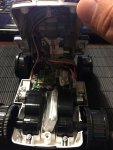
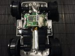
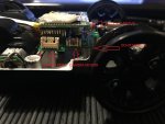
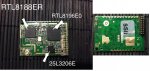
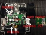
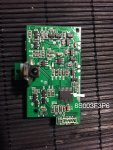
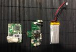
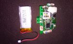
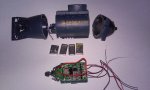
I kinda hacked a ispy tank my kids had around. Guts shows wifi module and maybe a DChip board with 2 motor outputs. But motors only run fowards reverse and multimeter shows 0v or 3.80 and -3.80v reversed. Nothing in between!

Bottom line, does anyone knows of an wifi module that can talk to my iPhone and picaxe?
 

BeanieBots

Moderator
I would second the ESP8266. Very cheap, very simple. A large choice of languages including BASIC and plenty of open source examples. Also, some friendly forum members who also hang out here.
 

PieM

Senior Member
ESP8266-01 : only 1 GPIO !
ESP8266-12 : 12 GPIO + 1 ADC


Besqueut said:
not clear to known if it is 4 Mbytes=32 Mbits or 4 Mbits...

  • Breakthrough design, there are new breakthroughs, based on ESP-12E.
  • The new four-layer board design.
  • The new revision antenna RF performance optimization, communication distance is increased by 30% -50% compared to ESP-12E!
  • Semi-hole chip technology, the whole IO leads, with metal shielding shell
  • Passed FCC & CE & RoHS certification
  • Built-board PCB antenna
  • 4M bytes SPI Flash for programming.

    see : http://www.electrodragon.com/product/esp-12f-esp8266-wifi-board/
 
Last edited:
For your wish :

Via my iPhone control an rc car using wifi not bluetooth,control motors speed.
You only need a ESP8266-01 and a picaxe.
In German it is an old hat .

it was just a tip times to have a look , how you can do it
but you can also make unnecessarily difficult
and buy what does not necessary
 

xtech007

Senior Member
thank you guys!

Sorry for the delay, I did order the chip mentioned above and started to mingle with the app also mentioned!
Will use a 28x2 to experiment.
But the next issue will be Video.

But I would really like to hack this Ispy mini tank. Well use its guts and video cam module!
Besides the app is great, control the vehicle and displays the cam in one app. I did opened the little bugger and this is what I found:
Wifi antenna with wifi card, and a DCHIP card attached. The DCHIP card controls the motors( 2) and 1 for the cam. Will post pictures when we get home. The DCHIP card uses a
STM8S003F3P6TR IC.
I wonder in this can be hacked or get data of it from the app. Hummm
Here is the link: it mentions a SWIM debug port also Uart.
http://www2.st.com/content/st_com/en/products/microcontrollers/stm8-8-bit-mcus/stm8s-series/stm8s003-005-007-value-line/stm8s003f3.html
 

xtech007

Senior Member
srnet, thanks for the Interest!

so far all I have is readings straight from the motor outputs.
With the app running on the iphone and push fwd stick, the meter reads 3.8 vdc, on both motors outputs.
When push Reverse stick ,both motor outputs reads -3.8 vdc.
When the left stick is pushed one motor output reads 3.8vdc and the other -3.8vdc hence turns left. same goes when stick is pushed to the right.
Like mentioned earlier voltage readings from the motors outputs are only 0V ,3.8v,and -3.8 nothing in between.

Experimented using the LEDS outputs!
the board have 2! when white are "ON" motors move FWD when red are "ON" Motors move reverse.
so programed my 28x1 to read pin1 and pin2 if any is high move motor on that direction, great WORKS!!!!!!!! simple!
BUT after a little Victory Dance, it kicked me how about speed!! or LT & RT and also speed there too..

With that said, and a large magnifying glass looked at the IC's on both modules for hope.
There are 2 modules: wifi and a DChip.
To be honest I have read Hours of datasheets but the little I know about electronics and data signaling is thanks to the folks here in the forum.
I would not know what would be the proper way or from where to get the data, the wifi module or the DCHIP module.

on the dchip module there is an IC (8S003F3P6)
http://www2.st.com/content/st_com/en/products/microcontrollers/stm8-8-bit-mcus/stm8s-series/stm8s003-005-007-value-line/stm8s003f3.html
that interfaces with UART, SPI, & I2C maybe here is where the data be read.

I would think the wifi module would be much more complicated, 3 Ic's and seemed to be aimed towards IP-stack protocol encapsulating and decryption of the data from the app.

Here are some pictures of the Beast:
A.jpgB.jpg
 

erco

Senior Member
Yup, that's the guts of Happy Cow's 777-270 mini wifi tank with the internal 450 mAh LiPo. It's a great item, I have no idea how they can sell that for $26, free shipping! http://www.ebay.com/itm/Wifi-i-spy-RC-Tank-Car-RC-Camera-Car-777-270-w-Camera-for-Phone-Controller-T7L7-/401105579862?hash=item5d63c16f56:g:slAAAOSwKfVXDvv W

I've hacked one of those previously. Careful, there are more pins on the WiFi board than on the mainboard socket, so when reassembling, align the OUTER pins along the PCB edge. The unused pins hang out in the breeze between the camera connector & raise/lower motor connector.

Today I hacked another Happy Cow toy, their submarine. The toy is great as-is, and the fact that it costs $10 and has a nice 3-channel, 40 MHz RC control system makes it the cheapest controller in town.

http://www.ebay.com/itm/Mini-RC-Submarine-with-Double-Propellers-Black-/291744753761


Attachments

Last edited:

erco

Senior Member
Your app looks slightly different than mine (Android), is yours iPhone? Mine has another icon, a bar graph showing battery condition/voltage in the vehicle, which I think is very cool, sending telemetry back. It's some kind of ADC obviously. I'd love to hack that too, for instance, to send other info back, perhaps distance/range from a Sharp IR distance module (analog output) to know how far away something is.
 

xtech007

Senior Member
erco, you are right ! I'm using an Iphone!
also did make note and took pictures of the pins you mentioned on the wifi module!

you mentioned "I've hacked one of those previously"
If I may ask, what was done and how?
did you interfaced with picaxe or just straight to motors?

my Goal would be able to get data from the app, control stick or gyroscope to the picaxe and run my own motors controlling speed and direction!
 

erco

Senior Member
I left both drive motors intact, but I wired the cam raise/lower wires to two Picaxe 08M2 input pins. They are normally high and go low when the buttons are pushed on the app. Everything was powered by the stock 450 mAH LiPo. Initially I had an 18 second pause in the program to allow for the WiFi startup time, then the Picaxe beeped a piezo to signal to signify ready, in addition to the flashing white LED near the camera lens. But the Picaxe resets itself occasionally, which would start the 18 second timer again. I couldn't eliminate the resets, I tried bigger filter caps, even disconnecting both motors, thinking it was voltage drop, but nothing helped. It might just be RFI from the WiFi transmitter, which as you know gets warm from power consumed and was in very close proximity to the Picaxe in my compact installation. The dipole antenna was also very close. In the end I just lived with the resets and let the program initialize as quickly as possible. Next time I'm in there I might try some aluminum foil shielding.
 

xtech007

Senior Member
You are correct about the pulse

Erco, you are right bout the pause at boot of the wifi module, clever to use the leds next to the cam for assurance when you are connected!
I have not noticed any disconecting or resets from the modules.

But,we are just using hardwire solution. Not complete Hack persay.
Any configration using leds or motor outputs still do not gives us speed control! Only full "ON" or "OFF"

Any Ideas?
 

erco

Senior Member
You'd probably have to modify the app for PWM and proportional speed control. It's sending full on commands by default.
 

xtech007

Senior Member
Humm.

I think the app sends position from 0-255, then the wifi modules receives that data then sends it to the DChip module, then if position is above or below a marked variable it turns the outputs on or off.

This is where we should be getting our variable!
 

xtech007

Senior Member
the data acquisition!

A good friend used a wifi data sniffer tool connected to a laptop where you can practically see the data packet being transmitted! From the app to the wifi module.
 

erco

Senior Member
Very useful info. The tank app may need modding for fine control of transmitting 0-255 variables. The control sliders (joysticks) are very small (short stroke). I use a 7" tablet and the total travel from center is still only about 3/8", or 3/4" from full reverse to full forward.

In comparison, the Cheerson drone app has long-travel sliders for fine control.
 

cachomachine

Senior Member
Just received my ESP8266-01 from china, (Wow 9 working days shipping) now what, cant find a data sheet, can't read a single word of german, anybody can help?
 

eclectic

Moderator
Just received my ESP8266-01 from china, (Wow 9 working days shipping) now what, cant find a data sheet, can't read a single word of german, anybody can help?
A simple Google search using the terms
esp8266-01 datasheet

shows several datasheets / starters..

e
 

cachomachine

Senior Member
Thanks, found a lot of info.

Good starting point, lots for arduino but nothing for Pixaxe

At least, i will have full learning and to play with.

My model is the one as of post #5
 

BESQUEUT

Senior Member
Good starting point, lots for arduino but nothing for Pixaxe
First challenge : send the AT command and receive the OK

If you have an FTDI USB/TTL, connect it as described (be carefull : 3,3 V power suply only)
Use a terminal emulator at 115200 bauds and type AT : you must receive "OK"

If you only have a Picaxe, you can use it to send the AT command, but you have to use the hardware serial interface to achieve 115200 bauds...
Later, it will be possible to reduce speed with the AT+UART_CUR command and use standard Picaxe serial interface.

You can simply ignore the Arduino stuff and send AT command directly from the Picaxe.
You can also have a look to the ESP BASIC...
 
Last edited:

Hemi345

Senior Member
All of the ESP-01 I have recieved are configured for 9600 baud. Try that too if 115200 doesn't work.
 

BESQUEUT

Senior Member
All of the ESP-01 I have recieved are configured for 9600 baud. Try that too if 115200 doesn't work.
OUPS !
You are true ! (115200 was for my esp-12F)
So with 9600 I think you can send the AT command directly from the Picaxe, and receive a nice "OK"
If so, the hardware part is done !
 

xtech007

Senior Member
Thank you All!

After lots of search and reading decided to go all hardwire!
Due to the time project needs to be completed.
My boy's baseball tournament 9U!!
And all of it has to fit on a cooler!
It's a Rc Party Cooler!

Reason I wanted to use the Iphone was to eliminate the need of many controllers, the Rc for steering , the leds controller, and radio too.
Though it would be easier to hack the tank, besides it has its own app implementation done and video was a plus!
So this is what was done instead.
Rc receiver to picaxe, picaxe to hbridge, 3 ch used 1 for steering, 1 for Fwd & Rev , and 1 to turn amp,Radio& LEDs strip on/off. Still use phone to connect via bluetooth to radio and DJ from it!
Here is the result:
http://youtu.be/G1Nw3inP-FI
 

xtech007

Senior Member
wagon!

Erco, I thought and laughed at it too!
But currently working on the wagon that the cooler will be howling!
 

xtech007

Senior Member
build price!

Well most of the components are recycled from previous projects!
But here they are:
Amp: $45
Car radio:$32
8" sub + 2 9" 3 way speakers =$90
H-bridge: $29
Rc receiver system 2.4ghz : $24
80 watt dc 12v motor : $35
Linear actuator $65
Ws2801 led strip : $12 (China)
2x 12v 12ah battery $50
Faithfull 28x1 picaxe worth a million!

The experience building it with my kids priceless!
 
Top