[color=Navy]#PICAXE [/color][color=Black]28X2[/color]
[color=Navy]#NO_TABLE
#NO_DATA[/color]
[color=Green]' Symbols
' =======[/color]
[color=Blue]symbol [/color][color=Purple]patPtr [/color][color=DarkCyan]= [/color][color=Purple]b2 [/color][color=Green]' The number of our current pattern[/color]
[color=Blue]symbol [/color][color=Purple]pattern [/color][color=DarkCyan]= [/color][color=Purple]b3 [/color][color=Green]' The pattern [/color]
[color=Blue]symbol OnTime [/color][color=DarkCyan]= [/color][color=Navy]200 [/color][color=Green]' Delay used in Pause for On time [/color]
[color=Blue]symbol OffTime [/color][color=DarkCyan]= [/color][color=Navy]200 [/color][color=Green]' Delay used in Pause or Off time
' Code starts here
' ================
' ================[/color]
[color=Purple]dirsB [/color][color=DarkCyan]= [/color][color=Navy]%11111111 [/color][color=Green]' Set port B to all outputs[/color]
[color=Blue]do [/color][color=Green]' Loop starts here
[/color][color=Blue]gosub [/color][color=Black]GetPattern [/color][color=Green]' Call the routine to get the next pattern
[/color][color=Blue]gosub [/color][color=Black]Print_Dot_Pattern [/color][color=Green]' Call the routine to send pattern to LEDs[/color]
[color=Blue]loop [/color][color=Green]' End of loop
' Subroutines
' ===========[/color]
[color=Black]GetPattern: [/color][color=Green]' This routine get the pattern
[/color][color=Blue]inc [/color][color=Purple]patPtr
[/color][color=Blue]if [/color][color=Purple]patPtr [/color][color=DarkCyan]> [/color][color=Navy]37 [/color][color=Blue]then
[/color][color=Purple]patPtr [/color][color=DarkCyan]= [/color][color=Navy]0
[/color][color=Blue]endif
LOOKUP [/color][color=Purple]patPtr[/color][color=Black],[/color][color=Blue]([/color][color=Navy]%10001[/color][color=Black],_
[/color][color=Navy]%01010[/color][color=Black],_
[/color][color=Navy]%00100[/color][color=Black],_
[/color][color=Navy]%00100[/color][color=Black],_
[/color][color=Navy]%00100[/color][color=Black],_
[/color][color=Navy]%11111[/color][color=Black],_
[/color][color=Navy]%00100[/color][color=Black],_
[/color][color=Navy]%00100[/color][color=Black],_
[/color][color=Navy]%00100[/color][color=Black],_
[/color][color=Navy]%01010[/color][color=Black],_
[/color][color=Navy]%10001[/color][color=Black],_
[/color][color=Navy]%00000[/color][color=Black],_
[/color][color=Navy]%00000[/color][color=Black],_
[/color][color=Navy]%11111[/color][color=Black],_
[/color][color=Navy]%00000[/color][color=Black],_
[/color][color=Navy]%00001[/color][color=Black],_
[/color][color=Navy]%00010[/color][color=Black],_
[/color][color=Navy]%00100[/color][color=Black],_
[/color][color=Navy]%01000[/color][color=Black],_
[/color][color=Navy]%10000[/color][color=Black],_
[/color][color=Navy]%01000[/color][color=Black],_
[/color][color=Navy]%00100[/color][color=Black],_
[/color][color=Navy]%00010[/color][color=Black],_
[/color][color=Navy]%00001[/color][color=Black],_
[/color][color=Navy]%00000[/color][color=Black],_
[/color][color=Navy]%00100[/color][color=Black],_
[/color][color=Navy]%01010[/color][color=Black],_
[/color][color=Navy]%10001[/color][color=Black],_
[/color][color=Navy]%01010[/color][color=Black],_
[/color][color=Navy]%00100[/color][color=Black],_
[/color][color=Navy]%01010[/color][color=Black],_
[/color][color=Navy]%00100[/color][color=Black],_
[/color][color=Navy]%01010[/color][color=Black],_
[/color][color=Navy]%00100[/color][color=Black],_
[/color][color=Navy]%00000[/color][color=Black],_
[/color][color=Navy]%10101[/color][color=Black],_
[/color][color=Navy]%01010[/color][color=Black],_
[/color][color=Navy]%00000[/color][color=Blue])[/color][color=Black]_
,[/color][color=Purple]pattern[/color]
[color=Blue]return[/color]
' =====================================================================
' Subroutine to operate the LEDS/Solenoids
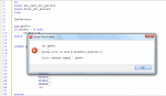
[color=Black]Print_Dot_Pattern:
[/color][color=Green]'
' Put code to drive LEDS here
'
' It is just 4 lines if you use the instruction on page 18 of manual 2
'
'[/color]
[color=Blue]return [/color]
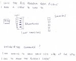
") Check your manuals...
Check your manuals...