Hi,
In principle, it need be no more difficult for a PICaxe to measure the (direct) current flowing in an external component (or module) as it is to measure an external voltage. Basically, we can just read the voltage across an external resistor and use Ohms Law (I = V/R) to calculate the current. In the same way that we normally measure external voltages relative to "Earth" (0 volts), the current-sensing resistor normally would be connected to Earth. But the Supply Rail (Vdd) might be used, or even a "differential" measurement using two ADC input pins is possible.
However, we may need to be more careful with the choice of component values than a simple voltage measurement, particularly if we are introducing an additional resistor into the circuit, purely for the purpose of measuring the current flow. In this case the voltage drop across the resistor is "lost" from the drive voltage, so needs to be no more than (say) 10% of the supply rail. Another factor to consider is that the power dissipation in a resistor is proportional to the SQUARE of the current (or voltage) applied, so we need to be aware of the MAXIMUM current which is likely to flow in the circuit.
If the likely maximum current is not known (or is much higher than the nominal value which needs to be measured), then a forward diode can be connected across the sensing resistor. A normal silicon diode will limit the voltage drop (and thereby the resistor power dissipation) to about 600 mV, but in some/many cases a "Schottky" diode is a better choice, typically limiting the voltage to just a few hundred millivolts.
However, if the (default) Vdd supply rail is used as the reference voltage for the ADC, and the maximum voltage that we can measure is less than 10% of the supply rail, then even a READADC10 returns a value only up to about 100. Therefore, even (or perhaps particularly) if the supply rail is regulated (e.g. to 5 volts) then it can be beneficial to increase the ADC sensitivity by using a lower reference voltage such as the 2 volt Fixed Voltage Reference (FVR2048).
The PIC(axe) data sheets specify that the 1 volt FVR should NOT be used for the ADC reference voltage, but several people have reported using it successfully. For measuring current, it may well be entirely satisfactory, because the typical source impedance is low (ohms) and only part of the full voltage range of the ADC will be used. There are issues with using FVR1024, but they are probably not relevant here, so I will describe them elsewhere.
Thus, the external current can be measured by a program snippet such as:
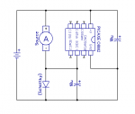
The ADC makes an "instantaneous" measurement so it's important to ensure that there is not excessive ripple on the ADC input. Generally, a decoupling (or reservoir) capacitor should be across the EXTERNAL circuit (e.g. with its negative terminal connected to the top of the current-sense resistor). A capacitor connected directly across the (low impedance) current-sense resistor is unlikely to achieve any useful filtering (i.e. averaging) action, so if ripple on the sense resistor is significant then add a R-C low-pass filter onto the ADC input of the PICaxe, as shown in the diagram below.
I had intended to include a simple diagram showing just the current-sense resistor and filter/limiting components, but it "grew" to show in context all the related components that MIGHT be used (except for the usual PICaxe serial programming circuit). However, the 1 ohm (typical) resistor is the only "fundamental" component required to measure the average current flowing from the battery and passing through the load. The "optional" voltage-limiting (Schottky) diode, low-pass filter (10K + 100 nF) and power decoupling (100 uF) have been mentioned already.
The load (e.g. a small motor) could be switched (on/off or with PWM) by the "darlington" transistor (which might be a single package or two separate components), but alternatively could be a single bipolar transistor or a FET. If the load is inductive (such as a motor) then the "Flywheel" diode is necessary, to prevent an excessive voltage being generated when the transistor switches off. The optional 10 ohm (typical) resistor is included in the supply rail to "encourage" the current to flow into the 100 uF "power" reservoir capacitor, rather than upset the voltage on the PICaxe supply rail.
Part 2, using a capacitor for smaller currents, will follow in due course.")
Cheers, Alan.
In principle, it need be no more difficult for a PICaxe to measure the (direct) current flowing in an external component (or module) as it is to measure an external voltage. Basically, we can just read the voltage across an external resistor and use Ohms Law (I = V/R) to calculate the current. In the same way that we normally measure external voltages relative to "Earth" (0 volts), the current-sensing resistor normally would be connected to Earth. But the Supply Rail (Vdd) might be used, or even a "differential" measurement using two ADC input pins is possible.
However, we may need to be more careful with the choice of component values than a simple voltage measurement, particularly if we are introducing an additional resistor into the circuit, purely for the purpose of measuring the current flow. In this case the voltage drop across the resistor is "lost" from the drive voltage, so needs to be no more than (say) 10% of the supply rail. Another factor to consider is that the power dissipation in a resistor is proportional to the SQUARE of the current (or voltage) applied, so we need to be aware of the MAXIMUM current which is likely to flow in the circuit.
If the likely maximum current is not known (or is much higher than the nominal value which needs to be measured), then a forward diode can be connected across the sensing resistor. A normal silicon diode will limit the voltage drop (and thereby the resistor power dissipation) to about 600 mV, but in some/many cases a "Schottky" diode is a better choice, typically limiting the voltage to just a few hundred millivolts.
However, if the (default) Vdd supply rail is used as the reference voltage for the ADC, and the maximum voltage that we can measure is less than 10% of the supply rail, then even a READADC10 returns a value only up to about 100. Therefore, even (or perhaps particularly) if the supply rail is regulated (e.g. to 5 volts) then it can be beneficial to increase the ADC sensitivity by using a lower reference voltage such as the 2 volt Fixed Voltage Reference (FVR2048).
The PIC(axe) data sheets specify that the 1 volt FVR should NOT be used for the ADC reference voltage, but several people have reported using it successfully. For measuring current, it may well be entirely satisfactory, because the typical source impedance is low (ohms) and only part of the full voltage range of the ADC will be used. There are issues with using FVR1024, but they are probably not relevant here, so I will describe them elsewhere.
Thus, the external current can be measured by a program snippet such as:
Code:
#picaxe 08M2 		; Or other M2s (and X2s with some modifications)
#no_data

symbol IRES = 1		; Value of current-sense resistor (in Ohms)
symbol Itest = c.1	; ADC input pin to test for current (relative to Ground/Earth pin
symbol Vext = b1	; Voltage across current-sense resistor (generally a byte will be sufficient)
symbol Iext = b2	; External current in sensing resistor (milliamps)

   fvrsetup FVR1024	; Set the Fixed Voltage Reference to (nominally) 1.024V
   adcconfig 3		; Use the FVR as ADC (positive) voltage reference (M2 only)
   readadc10 Itest,Vext	; Read the voltage drop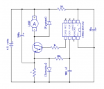
Iext = Vext / IRES ; Current in mA (resolution = 1 mA)I had intended to include a simple diagram showing just the current-sense resistor and filter/limiting components, but it "grew" to show in context all the related components that MIGHT be used (except for the usual PICaxe serial programming circuit). However, the 1 ohm (typical) resistor is the only "fundamental" component required to measure the average current flowing from the battery and passing through the load. The "optional" voltage-limiting (Schottky) diode, low-pass filter (10K + 100 nF) and power decoupling (100 uF) have been mentioned already.
The load (e.g. a small motor) could be switched (on/off or with PWM) by the "darlington" transistor (which might be a single package or two separate components), but alternatively could be a single bipolar transistor or a FET. If the load is inductive (such as a motor) then the "Flywheel" diode is necessary, to prevent an excessive voltage being generated when the transistor switches off. The optional 10 ohm (typical) resistor is included in the supply rail to "encourage" the current to flow into the 100 uF "power" reservoir capacitor, rather than upset the voltage on the PICaxe supply rail.
Part 2, using a capacitor for smaller currents, will follow in due course.
Cheers, Alan.
Last edited: