Connecting 2 pins together

oracacle

Senior Member
The title doesn't do this much justice but cant think what else to title it.

My current project to create a comprehensive set of sensors keeps running into the same snag, primarily due to the fact that a single wire is doing 2 way coms and each sensor has to be able to through pass instructions.
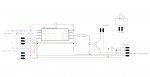
The problem that keeps coming up is the fact that there is often a need to be able to listen to a signal while also sending a signal. The attached circuit is the one in use with the exception that C.2 is tied low with a 10K.

C.4 goes to the previous sensor (or main controller) and C.2 goes to the next sensor (is there is one there). there could in theory be a max of 255 sensors in a chain, this will never happen as I do not need that many, nor do I have the energy to make that many.

C.2 has to listen to signals from the next sensor, as well as send them. this is fine for the fact it will spend it time listening while briefly sending "all clear" type signals.
C.4 on the other hand has to send a high or low signal depending on the state of the sensor, but as it currently stands also has to listen for a "all clear" type signal back.
The all clear is normally as simple has pulling the line high. After initialisation and instructions, there is currently only high low signals on the line.

I am thinking that if I connect C.4 and C.5 together and only listen for a high/low on C.5 when C.4 is set as an output and set low (care would need to be used to ensure this is done) but am unsure if this would cause an issue or what protection could or should be used to avoid catastrophe.

there is a part of me that I toying with moving the system to 14M2s and increasing the wire count. it would be the simplest route but have 2 sensors made up on strip board, and sourcing 4 wire connectors and cables. granted they can be repurposed as slightly less intelligent sensors that can be used with me timer or something.
 

Attachments

nick12ab

Senior Member
C.2 has to listen to signals from the next sensor, as well as send them. this is fine for the fact it will spend it time listening while briefly sending "all clear" type signals.
C.4 on the other hand has to send a high or low signal depending on the state of the sensor, but as it currently stands also has to listen for a "all clear" type signal back.
The all clear is normally as simple has pulling the line high. After initialisation and instructions, there is currently only high low signals on the line.
So it operates on the basis that a high pin will be connected to a low pin at certain times?

This system needs a rethink - consider using open drain outputs instead with a pull-up to power. The pin changes between input and low, never high, and you can tell if the other device is communicating as the bus will go low even though you are not driving it low.

I am thinking that if I connect C.4 and C.5 together and only listen for a high/low on C.5 when C.4 is set as an output and set low (care would need to be used to ensure this is done) but am unsure if this would cause an issue or what protection could or should be used to avoid catastrophe.
That will not result in any improvement, as reading from an output pin already does this because the input buffers are always connected even when a pin is in output mode.
 

bobladell

New Member
Check out PULLUP

Take a look at :-
PULLUP OFF (= PULLUP 0)
PULLUP ON (= PULLUP 255)
Function: Enable or disable the internal weak pull-up resistors on the target device.
Information:The pullup command can enable/disable the internal pull-up resistors on some input pins.

If you tie C.x high with the 10K, or any value down to say 1K depending on the drive capability of your sensor, then you can tie an I/P and the Pullup disabled O/P together (C.x set high) with no problems. Alternatively put a 330R in series with the O/P pin and it will pull the sensor low to start it off and not damage anything when being driven at 3V or 5V as PICAXE pins can source and sink 20mA.

I've used the same trick before on a 28X to drive a DHT11 / 22 temp / humidity sensor as the PICAXE pins can't turn from being O/Ps to I/Ps fast enough for the DHT and similar single wire sensors. Have a search for that DHT post and it will show you the code used for that project, with credits to Hippy and others, as I recall. Do a hardware wire OR by using a few diodes on one O/P pin, to allow a series of sensors to be triggered together and use one I/P pin per sensor. The internal structure of M2 series PICAXEs makes this even slower so even at 32MHz they are too slow to do the same thing for DHT sensors. Has to be an X series with the fastest external resonator to run at 64MHz.

If you want loads of sensors then cheapest is to go for multiple PICAXEs to get the speed, e.g. for DHT's, then link them on serial ports to a central PICAXE controller to aggregate the results and compute whatever you need to do from there. Port expanders might not be fast enough for the sensors, depending on the sensor - take a look at the sensor data sheets before going that route.

Bob
 

AllyCat

Senior Member
Hi,

As nick has already said, if you're attempting to communicate in two directions on a single wire/pin then you should/must use a "Wired Or" configuration, as employed by many protocols such as the I2C bus. The name is slighly misleading because it's an "Active Low OR" with one resistor (or more) pulling the line high and then any one pin can pull it low. It's "safe" for more than one pin to pull low at the same time, but not particularly useful because not possible to identify which pin is actually pulling low.

I don't think the Weak Pullups are particularly useful in this application because it's still neceassary for the PICaxe (software) to switch directly from an Output Low condition to an "input" (high impedance) state (to allow the resistor to pull the line High). Alternatively, you can use a hardware method, connecting a diode (cathode) to each pin (to pull the line down) and a single external pull-up resistor.

But have you considered the "fault tolerance" of such a system? What happens if the hardware or software of any one of the intermediate PICaxes turns "belly up"?

However, IMHO there is plenty of scope for a more sophisticated (and resilient) communications protocol even with 08M2s. You don't appear to be using the Serial (programming) Input and Output pins, nor many of the chip hardware features such as the Set-Reset Latch, hardware UART, "Data Signal Modulator", Timer 1 Gate (which can be used as a Latch), Capture-Compare Latch and of course the I2C hardware, etc.. Also note that even the Serial Output pin can be used as an input (it has a secondary function of DAC output which is readable) and all pins (including "input only") can provide a limited (and safe) output capability using the Weak Pullup resistors.

Cheers, Alan.
 

oracacle

Senior Member
each of the sensors on the chain go through a relatively complex initialisation so that it know where it is on the chain, is the data is not correct then a dumb sensor system is activated an only the sensor can be an input and C.4 is an ouput.

here is the sensor initislistion
Code:
'####################################
'#######Sensor Startup Squence#######
'####################################
	pause 200						'allow controller start up
	let dirsc = %000110				'set c.1 and c.2 as ouput
'###Now Setup sensors###
	setfreq M16
	let address = 0					'set defualt address
	let instruct = $05				'set defualt instruction - and on all sensors
'controller to pull contin pin of first sensor high
	if contin = 0 then				'check for controller signal
		'wait for address information from other sensors
		'if controller signal is not recieved
		let flag = 1				'set not first sensor flag
		serin [2000,start_laser], sercon, baud, (qual),address
								'if no controller detected, presume standalone sensor and skip ahead
								'default sensor setting so can be used as 'dumb' sensor - should work with timer.
		inc address					'increment address from previous sensor
		serout sercas, baud, (qual)		'send out next address
		pause 4
		serout sercas, baud, (address)	'send out next address
		let dirsc = %010010
		serout sercon, baud, (qual)		'send qualifier to previous to show attatched	
	else							'other wise fist sensor, send address to next sensor
		let flag = 0				'set first sensor flag
		pause 1000
		serout sercas, baud, (qual)
		pause 4
		serout sercas, baud, (address)
	end if
	'prepare to send signal to controller and resieve from other sensors
	let dirsc = %010010				'set c.2 and c.4 as outputs
	serin  [500,last_sens], sercas, baud, (qual)
								'what for signal from other sensors, other wise go and set flag before returning
last_sens_return:	
	if flag = 2 then					'flag 2 indicates last sensor
		pause 1000					'wait for controller to be ready to recieve signal
		serout sercon, baud, (qual)		'now send data to controller		
		pause 4
		serout sercon, baud, (address)	'send address to previous sensor
	else							'else either first of not last sensor
		serin sercas, baud,(qual), number	'receive
		if flag > 0 then				'if not first sensor then send previous address on to next sensor
			serout sercon, baud, (qual)	'send data
			pause 4
			serout sercon, baud, (number)
		end if
'###now final handshake with controller###
		do while contin = 1			'check to see if controller has set sensor pins low
		loop						'stay here until controller is ready
		pause 200					'wait for controller to listen for echo
		high contout				'send signal back to controller so it knows what pin to listen to
		pause 200					'hold high for period to ensure signal heard
		low contout					'switch of pin
	'now tell controller how many sensor are connected	
		pause 1000
		'debug
		let dirsc = %010010			'set pins correctly
		let number = number + 1			'total number of sensors
		serout sercon, baud, (qual,number, type)
								'now send information to controller
	end if
'####################################
'###End of Sensor Startup Sequence###
'####################################
This code determines the sensors position in the chain, defines each address and informs the first sensor in the chain how many sensors there are. It should also resolve issues of faults in the systen
the problem I am now going to run into is that I need to keep the system fast as possible which goes some way to ruling out serial comms for beam break detection and certain operational modes mean that sometimes the issue may never arise.


Code:
$01	'Dumb' sensor
$02	laser Aiming
$03	Order -> Furthest to closest
$04	Order -> Closest to furthest
$05	And  
$06	Or
the and function is looking like it is the most tricky. due to the fact that this is for photographic purposes, the lasers need to be switched of for the duration of the shutter time, which can be pre-set by the controller. However all sensors need to know the state of the sensors on either side of them while also telling them sensor ahead of it (connected to c.4).
so:
sensor on c.2 receives low signal (driven low by next sensor)
it then drives c.4 low if its beam is broken too, other wise it stays high
once both the beam and next sensor are reading detection c.4 goes low informing the previous sensor
at this point I need to be able to listen to a complete chain signal from previous sensor while also checking the next sensor and laser
once the chain complete signal come back the lasers on all sensors are switched off.

I am going to have a bit more of a think, atm I am thinking, send a signal and wait while monitoring everything, and the previous sensor assumes everything is still OK unless told other wise.

in theory the sensor could easily out run the max specified length of I2C.
I am not sure what pullup will achieve
also bobladell each sensor has its own 08M2. I am building sensor that able to make a decision about what is going on depending on the other sensors and its own beam. the decision it makes depends on what instruction has been given to it
I generally avoid using the programming connections, its just a preference more than anything, however using it would allow for an extra data line in each direction giving full time bi directional communications - providing I can find appropriate leads and jack for at least 4 wires, which I have struggled with in the past and is one reason I have been using single wire bi directional comms.
Just getting the handshake on initialisation was hard work and took a fair bit of time, something that would have been quick with 2 data lines. But I do like a challenge from time to time
 

AllyCat

Senior Member
Hi,

... the lasers need to be switched of for the duration of the shutter time,
----
... providing I can find appropriate leads and jack for at least 4 wires,
Seems to me that perhaps you should use/add a common bus structure which supports a few "global" commands?

----

Yes, I had an idea that after re-programming an 08M2 (in a box), to re-use the standard 3.5 mm socket for a 3-wire DS 18B20 temperature sensor cable. It is possible (with a few minor modifications) but I decided to use the 4-wire version as for mobile phone and similar applications (Earth plus microphone and L/R earphones).

Individual plugs are a little pricey (I wanted a 90 degree type) so bought a double-ended cable for just over £1 (price seems to have gone up) and matching PCB socket for about 40p (switched versions also available) from CPC. ;)

Cheers, Alan.
 

hippy

Technical Support
Staff member
It is simply not possible to have a digital bus line indicate more than two states but an analogue bus can.

By using a pulled-up analogue bus it can indicate when none, one or both of the devices are pulling it low. The reading device knows whether it is pulling the bus down so, for the case of "one", it can work out if it is itself pulling the bus down or the other.

Untested ...

Code:
;             --.-- V+
;              .|.
;              | |
;  .-------.   |_| R                   .-------.
;  |       |    |                      |       |
;  |   ADC |<---^--.-------//-----.--->| ADC   |
;  |       |      .|.            .|.   |       |
;  |       |      | |            | |   |       |
;  |       |      |_| R        R |_|   |       |
;  |       |       |              |    |       |
;  |   OUT |-------'              `----| OUT   |
;  |       |                           |       |
;  `-------'                           `-------'

Symbol OUT    = C.x
Symbol ADC    = C.y

Symbol adcVal = b0
Symbol outBit = b1

Do
  outBit = 0 : Gosub SetOut : Gosub CheckAdc : Pause 1000
  outBit = 1 : Gosub SetOut : Gosub CheckAdc : Pause 1000
Loop

SetOut:
  If outBit = 0 Then : Low   OUT : End If
  If outBit = 1 Then : Input OUT : End If
  Return

CheckAdc:
  ReadAdc ADC, adcVal
  Select Case adcVal
    Case > 192
      SerTxd(   "Me = High", 9, "Other = High", CR, LF )
    Case > 105
      If outBit = 0 Then
        SerTxd( "Me = Low",  9, "Other = High", CR, LF )
      Else
        SerTxd( "Me = High", 9, "Other = Low",  CR, LF )
      End If
    Else
      SerTxd(   "Me = Low",  9, "Other = Low",  CR, LF )
  End Select
  Return
Also untested but should allow the concept to be tested with just a single PICAXE ...

Code:
;             --.-- V+
;              .|.
;              | |
;  .-------.   |_| R
;  |       |    |
;  |   ADC |<---^--.----------.
;  |       |      .|.        .|.
;  |       |      | |        | |
;  |       |      |_| R    R |_|
;  |       |       |          |
;  |   OUT |-------'          O |_
;  |       |                    |_|
;  `-------'                  O |
;                         0V _|_ 

Symbol OUT    = C.x
Symbol ADC    = C.y

Symbol adcVal = b0
Symbol outBit = b1

Do
  outBit = 0 : Gosub SetOut : Gosub CheckAdc : Pause 1000
  outBit = 1 : Gosub SetOut : Gosub CheckAdc : Pause 1000
Loop

SetOut:
  If outBit = 0 Then : Low   OUT : End If
  If outBit = 1 Then : Input OUT : End If
  Return

CheckAdc:
  ReadAdc ADC, adcVal
  Select Case adcVal
    Case > 192
      SerTxd(   "Me = High", 9, "Button = Released", CR, LF )
    Case > 105
      If outBit = 0 Then
        SerTxd( "Me = Low",  9, "Button = Released", CR, LF )
      Else
        SerTxd( "Me = High", 9, "Button = Pushed",   CR, LF )
      End If
    Else
      SerTxd(   "Me = Low",  9, "Button = Pushed",   CR, LF )
  End Select
  Return
 

oracacle

Senior Member
Thanks guys, got some stuff to think about
Thanks for those link, could prove useful.
If I am going to rebuild the sensors to make use of a new bus, there is a small part of me that is playing with idea of use a 9 pin d-sub which would leave space for further comms lines of they are ever needed.
 
Top