Resetting Thyristors Picaxe

Jamiestyles

New Member
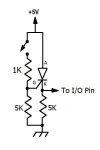
I am using a Thyristor to monitor an input. When the input goes high the thyristor goes on and the Picaxe increases the variable. I can't use an interrupt because most of the program is using COUNT and it doesn't register the momentary high of the switch during the COUNT function.

I obviously need to reset the Thyristor after the variable has been increased and I have been using a Transistor to cut the current to reset it.

I've been using the following circuit for a while and it works fine and reliably although I am aware it is probably not best practice. Its current draw is also quite high:

FullSizeRender.jpg


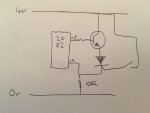
To save on components would this work or is it really bad practice?
FullSizeRender-2.jpg


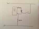
What is the best way to reset a thyristor using a Picaxe?

Many thanks in advance for your help.
 

techElder

Well-known member
You shouldn't use hardware to fix software problems. Besides, you aren't triggering that SCR properly.

We can't help you with a coding problem if you don't supply the code, Jamiestyles.

I can think of many ways to solve those kinds of problems, and most of them are available here on the forum. Have you searched for "count"?
 

Jamiestyles

New Member
You shouldn't use hardware to fix software problems. Besides, you aren't triggering that SCR properly.

We can't help you with a coding problem if you don't supply the code, Jamiestyles. "

I don't think this is a coding problem. I am happy with the COUNT function. The problem is that the Picaxe spends 99% of its time counting using COUNT, during which the Picaxe doesn't/can't listen for an interrupt. Hence, I need to have the momentary input latch on until the COUNT has finished. At this point it has to increase a variable by one then reset the thyristor.

Can you elaborate what's wrong with my SCR cuircuit?
 

techElder

Well-known member
You may know what you are doing ... but others probably don't.

Can you elaborate what's wrong with my SCR cuircuit?
I'm not going to get into that without knowing what your software is doing.
 

Jamiestyles

New Member
You may know what you are doing ... but others probably don't.


I'm not going to get into that without knowing what your software is doing.
The software counts how many times a pedestrian gate opens in 60 seconds using COUNT. Typically about 15 times.

At the end of every 60 seconds it checks if another input pin in high to see if the vehicle gate has been used. This input currently latches high using a thyristor. If it has it increases a variable using an IF and INC command then goes back to counting the pedestrian gate having reset the thyristor.

It then sends the number of opens and closes of the person gate and vehicle gate to a php script on a server
 

rossko57

Senior Member
If events are only happening every few seconds, using COUNT may not be the only approach. Presumably inputs are from microswitch or beam-break or similar? Durations of tens or hundreds of milliseconds? There would be plenty of time to monitor multiple inputs and count (by program) and monitor a minute passing, without special hardware. Should also deal better with the case of two vehicle movements within a minute.

Some Picaxe feature an SR flipflop which can be used to capture transients, but its probably not needed here.
 

Jamiestyles

New Member
Thanks. I'll look into SR Flip

It is just two simple microswitches. I can see there are lots of different ways to get the same result. The count just made it easy to monitor flow per hour without using timers. The vehicle gate takes more than a minute to open and close.

I'm happy with using the thyristor and it has worked flawlessly for over a year. I'm just very conscious it's not the best practice. What is the best way to interrupt the current flow through the thyristor using a Picaxe rather than a switch?
 

erco

Senior Member
SCRs are fun to play with. You can also shut off an SCR by briefly shorting the AK terminals together, which drops the SCR below its minimum holding current.

You can probably delete the transistor from your circuit and use just one tristate I/O pin.

IIRC the Picaxe SRLatch is hinky. It can't be read (or is it reset) directly by the Picaxe, requires a extra pin.

But TTYTT for your application, it doesn't sound like any external hardware is needed. Other than bounce, your switches are opening and closing glacially slow by Picaxe standards and can surely be read reliably by fast polling.
 
Last edited:

Jamiestyles

New Member
Thanks. They are good fun. Agreed. If I stick with a SCR would the powering it off an I/o pin be bad practice. Can the shorting of the anode and cathode be down with a transistor and suitable resistor?

If I look to do it with software is there a 20X2 equivalent of setimer count xxxxx I see the X20 can't use an external counter (Sod's law) ;)
 

eggdweather

Senior Member
There is not much wrong with your original circuit. Ideally Igate needs to be limited to the gate current limit (Ig-max), but you have a load in the cathode of the SCR, so that limits gate current, there being no other current paths. Powering from an I/O pin is not good practice, unless the load current is much less than the absolute maximum of the PICAXE source-current rating. Using PICAXE interrupts should give you a much more elegant solution then your current (assumed) scheme. You can run two programmes in (pseudo) parallel, so you could detect in one and count in another, but I expect so-called blocking commands are global across all running programmes.
 

AllyCat

Senior Member
Hi,

IMHO neither a thyristor nor the (blocking) COUNT instruction can be considered "best practice" when it can be done with simple polling software and NO external hardware (except perhaps a resistor in series with the pin to "protect" the PICaxe).

IIRC the Picaxe SRLatch is hinky. It can't be read (or is it reset) directly by the Picaxe, requires a extra pin.

But TTYTT for your application, it doesn't sound like any external hardware is needed. Other than bounce, your switches are opening and closing glacially slow by Picaxe standards and can surely be read reliably by fast polling.
Yes indeed, the on-chip SR Latch hardware is rather limited, with only one input pin, two output pins (at most) and no ability to read it directly by software. :(

Certainly not for novices, but it you DO need to catch fast pulses efficiently, then I described how to emulate a software-readable Latch using the M2's Timer 1 Gate Hardware in posts #6 and #10 in this thread . ;)

Cheers, Alan.
 

techElder

Well-known member
Guys, it has already be stated that it is a SLOW application. There's certainly no need for even an interrupt.

Jamie, if you're using COUNT you are still using a timer.

What you need to make you comfortable is to become more educated on programming within a loop. Then within that loop you check your switch closures and accumulated them.

You can pad the loop so it is 60 seconds or you can learn another way to time events. It is your choice.

Aren't you just dying to add a display to show your count or display the average count?

But don't think that you have so difficult an application that you can't solve it without resorting to external hardware fixes.

Tell us what you really WANT to do. You can figure out how to short out an SCR to make it stop conducting. You don't need this forum for that.
 

erco

Senior Member
If I stick with a SCR would the powering it off an I/o pin be bad practice. Can the shorting of the anode and cathode be down with a transistor and suitable resistor?
I knocked up the attached circuit and it works fine. Not sure about "best practice", and I still say it's not necessary, but I like to play with simple hardware, especially when it saves an I/O pin. I used a small 800 mA SCR out of my junk box. A series 10K resistor would not allow it to latch, but 5K worked fine. That is, allowed enough holding current to stay on. The resistor values on the gate could use some experimentation, but these are safe values, the first ones I tried, and they worked. Connect to any I/O pin and monitor pin to see if the SCR is triggered (high or low). Reset SCR by briefly making the same pin high. 10 ms was plenty for mine.

Edit: Corrected schematic, changed SCR cathode resistor value from 47K to 5K, sorry for any confusion

Code:
do  ' SCR attached to 08M2 pin c.2
for b0=1 to 255
sertxd (#b0,"  ",#pinc.2,13,10)
next
high 2:pause 10:low 2 ' reset SCR
loop
 

Attachments

Last edited:

Hemi345

Senior Member
IIRC the Picaxe SRLatch is hinky. It can't be read (or is it reset) directly by the Picaxe, requires a extra pin.
The extra pin is needed to read the state. I use the In-only pin which is usually directly across from the SRQ pin.
 

hippy

Technical Support
Staff member
Though not supported directly, it is possible to use the SFR's to do edge detection on I/O pins even on an M2, effectively HINTSETUP without SETINTFLAGS. In the following example, taking input pin C.3 of an 08M2 high during the two seconds of putting dots up on the Terminal will be indicated after those dots -

Code:
#Picaxe 08M2
#Terminal 4800

; Interrupt On Change SFR
Symbol IOCAP = $F1 ; $391 - Capture positive edges
Symbol IOCAN = $F2 ; $392 - Capture negative edges
Symbol IOCAF = $F3 ; $393 - Capture flag

; Allow IOCAF bit to be set on Input C.3 going high
b0   = 0
bit3 = 1                     ; C.3
PokeSfr IOCAP, b0            ; Capture positives
PokeSfr IOCAF, 0             ; None captured so far

Do
  ; Delay a few seconds
  SerTxd( CR, LF )
  For b0 = 1 To 20
    SerTxd( "." )
    Pause 200
  Next

  ; Check if edge detected
  PeekSfr IOCAF, b0
  If b0 <> 0 Then
    PokeSfr IOCAF, 0
    SerTxd( " PUSHED" )
  End If    

Loop
 

AllyCat

Senior Member
Hi,

The extra pin is needed to read the state. I use the In-only pin which is usually directly across from the SRQ pin.
Yes, or it's also possible to use the Serial (Programming) Input pin (after a DISCONNECT). Sometimes, I link one of these input pins via a diode, so the pin also can be used for other purposes (typically, enabling it by activating the corresponding internal weak pullup resistor).

Though not supported directly, it is possible to use the SFR's to do edge detection on I/O pins even on an M2, effectively HINTSETUP without SETINTFLAGS.
Thanks hippy, that's interesting. Perhaps it's worth mentioning that the example code (in that format) can be used only with M2 devices and applies specifically to the PIC's "PortA" pins. With an 08M2, it happens (probably by design) that the Port C (aka Port B) pin numbers are the same as the base PIC chips's Port A, but this is not (necessarily) true for other M2 devices.

A useful feature of the "later" M2 devices (i.e. not 18M2+) is that the "top" 8 legs are "equivalent" at the base chip/SFR level. Thus, the 14M2's c.5, c.4 and c.3 (Legs 2 - 4) correspond to the 08M2's Legs 2 - 4 (i.e. b/c.5, .4 and .3) and the b.0, b.1 and b.2 pins (Legs N-1, N-2 and N-3, where N is the number of pins) correspond to the 08M2's Legs 7, 6 and 5 (i.e. b/c 0, .1 and .2).

However, it's rather more "messy" with the 20M2 because the 20M2 (sadly) doesn't have port.pin numbers allocated to the Serial Input and Output pins, so the pin numbers are shifted by 1 (or 2) relative to its "baby brothers".

Cheers, Alan.
 

hippy

Technical Support
Staff member
Yes, it can get messy with other PICAXE chips, and the PICmicro datasheets need consulting to map PICAXE pin names to underlying PICmicro names. On the 14M2/20M2 there are separate SFR's for PICmicro RAx and RBx pins, but 18M2/+ only supports RBx pins.
 
Top