Installing a reed switch

Bycroft

New Member
Hi,
I don’t know if anyone can help, I am a complete newbie to picaxe programming. What I am trying to do is. I have a small train layout, I want to put a reed switch in front of a train signal the signal should be on green, when the train goes over the reed switch the signal will change to red further along the track I want to put another reed switch to switch the signal back to red.
I want to use a Picaxe 08m+ or an 18M2 chip, I think I will need to install a pull up resistor on to the reed switches. Any help would be much appreciated.
Many thanks.
Dave
 

ZOR

Senior Member
Have you read Manual 3 (free download) page 26, interfacing to switches. You should find all your answers in this manual including interfacing LED'S etc.
 

Reloadron

Senior Member
You can use a reed switch or for that matter even a HALL Effect switch would be a good choice. You can use a PIC chip or for that matter a simple discreet component like a CD4013 D Flip Flop. There are several ways to do what you want to do. Anytime you use a mechanical switch like a reed switch note the advice from ZOR above and read about "switch bounce" on page 27 of the above referenced manual.

Ron
 

oracacle

Senior Member
it would be helpful to post a circuit diagram of what you have, or thinking of.

something very simple like an SR latch could be used for this, heck even a relay set as a latch could be used.
suffice to say, a 08m2 would easily be able to control something like this.

the pull up resistor would be needed if you are using the read switch to pull the input low, and a pull down if you intend to pull the input high. in each case you should, in theory at least have a protection resistor going into the pin.
do you intend to use a I bi-colour LED or two separate LEDs?
 

binary1248

Senior Member
Here is the code for a block signal control. I have a pc bd layout and built a couple of these. My desktop computer crashed so it may take awhile but I will also post the schematic later.
In the header of the code explains the operation.
Code:
;March 9 2014   PE HAUG
;   *************************
;   *HO Train Block Signal Cntl *
;   *************************
;
;
;  Reed senors entry block port 3 (physical pin 4)
;  Reed senors exit block port 4 (physical pin 3)
;
;enter entry block, unconditional red
;enter exit block, red off, yellow on
;10 sec delay yellow off, green on.
;
;
#picaxe	08M2
;
;

;
symbol redled=2 ;pin 5 on chip
symbol yelled=1 ;pin 6 on chip
symbol grnled=0 ;pin 7 on chip
	
symbol inblck=pin3   ;input pin 4 on chip
symbol outblck=pin4  ;input pin 3 on chip

Start:
	input 3,4         ;make ports 3 & 4 inputs
  ;little startup test seq lamps	
	
	for b1=1 to 10
	high redled
	pause 100
	low redled	
	high yelled	
	pause 100
	low yelled
	high grnled	
	pause 100
	low grnled
	next b1
	;


	;
	Main:
	;	Find 1st block entry switcg triped
red:	if inblck=0 then  ;physical pin 3
	high redled
	low grnled
	endif
	
	
	if outblck =0 then
	goto yellow
	else goto red
	
	endif
	
	;
	;Wait for 2nd senso
yellow: if outblck =0 then
	    low redled
	    high yelled
	  else goto green
	endif
	
green:	
	pause 9000  ;nine sec delay on yellow, then green

	low yelled
	high grnled
	goto main
 

binary1248

Senior Member
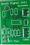
Here is the layout of the board, the backside is all gnd plane except for one power trace.
If your interested, I will post the schematic later, having to recreate it, lost original with PC crash.
IMG_0114.JPG
 

rossko57

Senior Member
Might be worth thinking through what will happen if/when the "rules" get broken.
example: 'exit' sensor triggered before entry - say a train is standing in the section before switch on.
example: 'entry' sensor trigger never followed by 'exit' - say a train is run through section in reverse.
example: 'driver asleep' - second following train enters section before first has cleared. Terribly naughty of course, but what state(s) will the signal go through?
You may or may not want to take different actions for these edge cases, and certainly don't have to when the signal is for show more than actual train control.
 

binary1248

Senior Member
Yep, it is strictly for show to replace the dummy signals that don't even light or just stay the same color. actual train/block control is for much later.
BUT, that is something I will consider for a later revision. Thanks for the heads up.
 

binary1248

Senior Member
Do you
think Bycroft will ever come back? He lives in North orkdhire?
It was his first and last (so far) post on this picaxe fourm. At the lest it got me to recover some lost code (PC crash) that I will need later for my son-inlaws HO train stuff.
 

ZOR

Senior Member
At least it was worth you putting the information up for others to use. It's a popular subject, and deserves praise for the logics involved in making it all work. Regards
 
Top