Bare bone microstepping?

edmunds

Senior Member
Dear all,

I'm doing a small modelling project - a windmill (modern type, makes electricity :)) in 1:87 scale that is actually supposed to turn. Turn slowly.

A DC brushed motor would require lots of gears to make it slow enough and there is no space for lots of anything in the windmills head. This would mean I would have to build some sort of shaft with 90 degree purchase. Not impossible, but prone to maintenance, precision problems and many hours of work.

I knew one kind of motor that can be slow without any extra hardware - stepper motor. And I found small enough :). Just had to wait a month for it to arrive. It has four wires and picaxe is running it happily directly (AXE091 drawing around 9mA) with the test code below:

Code:
#picaxe20x2

#no_data
#no_table

setfreq m64

Symbol delay = 700        'stepper motor delay, 7 to infinity are decent values, 400 is the slowest smooth rotation

dirsB = %00001111     'set four motor outputs

main:

  b1 = b1 + 1
  b1 = b1 & %00000011

  lookup b1, (%1010,%1001,%0101,%0110), b2

  pinsB = b2
  pause delay

goto main
While pause of 400 gives me smooth rotation it is about 30RPMs. I would need around 10RPMs for it to be perfect. Is there a crude microstepping implementation that I could use to smooth out slower rotation?


Thank you for your time,

Edmunds
 

edmunds

Senior Member
Wayne, great link, half-stepping seems entirely possible. Will try it out tomorrow morning (02AM here:)). Thank you!

@erco, thank you for the links, but the diameter of the motor I'm working with is about 6mm and length about 4mm. China is not a problem, this is where the tiny steppers are from, but size matters :). Thank you for your input!

Edmunds
 

techElder

Well-known member
Also, if the stepper doesn't prove to be usable, there are small diameter motors used in tail rotors on very small hobby helicopters. I think you can buy them from hobby sites. Very small.
 

edmunds

Senior Member
Also, if the stepper doesn't prove to be usable, there are small diameter motors used in tail rotors on very small hobby helicopters. I think you can buy them from hobby sites. Very small.
Tex, there certainly are, but they will be around 10.000-20.000RPM without gears. Thank you for your input, though.


Edmunds
 

AllyCat

Senior Member
Hi,

It has four wires and picaxe is running it happily directly (AXE091 drawing around 9mA)
From the link in WA55's post it seems that 4 quadrature-phased "sine waves" may be needed for microstepping. In principle that might be possible even with a modest PICaxe, using PWM, either the on-chip hardware or a software emulation.

But what is your ultimate target PICaxe hardware configuration? Do you know the impedance (resistance and inductance) of the stepper coils? I might have some similar steppers (which I've never actually tried to use) but the coils are only 20 ohms, so I would have expected the drive current to be quite high.

How did you measure your drive current? 9 mA seems hardly any more than I would expect a PICaxe core alone to use at 64 MHz.

Cheers, Alan.
 

goom

Senior Member
What about using a micro hobby servo modified for continuous rotation? They do come in quite small sizes (e.g 23 x 12.2 x 29 mm), incorporate all of the reduction gearing and are quite inexpensive.
 

edmunds

Senior Member
EDMUNDS, post a picture of your model, with a scale next to it. Be interesting to see your project in pictures.
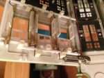
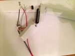
Fair enough, here you are - one of a windmill head, one of a building with opening windows, both HO scale, the motor in the windmill is actually smaller than that for the windows, but not by much. The chip in the windmills' head is a 20X2.

IMG_0690.JPGIMG_0691.JPG

Wayne - I got half-steps working, brilliant, good enough for the windmill project.

@AllyCat - that is what I figured, but did not quite understand how to get the timings right. Any pointers, please? :)

The current comes from a dirt cheap current meter fitted to my bench supply, formerly known as atx psu. it has been reasonably consistent with its brother multimeter, also chinese origin, however, so I believe it is quite right. I do not mind adding transistors in between or even a motor driver ic - have quite a collection of all kinds by now, but just cannot see the need. I know the chip is not resetting since it is flashing an LED correctly starting every 36th loop.


Thank you all for your input,

Edmunds
P.S. The picture of the building is head down for some reason on a computer. It is alright on the phone, though.
 
Last edited:

oracacle

Senior Member
Micro stepping needs a fair bit, there are plenty of drivers out there where all that is needed is to send a clock signal.
the problem you will face is obtaining the readings that you need to obtain a sine wave, and matching ADC values.
I did get a load of values from the THB6064 data sheet I used for a project so can provide current percentage values for half, 8, 16, 42, 64, 10, 20 and 40 step.
you need a non inductive resistor on the ground of each H bridge to act as a current sensor to feed into the ADC
its normal to run micro step drivers at least twice that of there rated voltage, coils are current driven. the stepper I used is rated for 2.3amps 2.7v coil, the driver runs of 7.2v with the logic running at 5v.

for an application like this, something like an easy driver, if you can find space for it, will be the simplest way to go, can be driven of a PWM signal, that can be generated by something like a 555. we all know 555 is cheap and easy driver is a few on ebay.
 

The bear

Senior Member
Hi Edmunds,

A small bipolar stepper 12x12mm sled driver out of a CD player, running off a 08M2 at a lower Setfreq in the 'k' region rather than 'm'.

Regards, Bear..
 

AllyCat

Senior Member
Hi,

Yes, I was surprised at using 64 MHz (and an X2 rather than 08M2) for such a "slow" application. Presumably the stepper is driven directly from the PICaxe pins? I'm surprised there is enough current to turn the motor, but 9 mA averaged at 25% duty cycle could be a 36 mA pulse, which is rather outside the PICaxe pin specifcation. However, with a 20 pin chip you could use up to 4 pins in parallel for each coil terminal. But don't switch the outputs directly from Low to High (or vice versa) but select a high impedance (input mode) in between.

I got half-steps working, brilliant, good enough for the windmill project.

@AllyCat - that is what I figured, but did not quite understand how to get the timings right. Any pointers, please? :)
So it's not worth going into much detail here. But the important thing is to appreciate the difference between the (PWM) switching frequency and the (potentially much slower) motor-stepping frequency. With the on-chip hardware that's largely done for you, but doing it entirely with software would probably use two "nested" loops (inner for PWM duty cycle, outer for stepping).

But first, I'd experimrent with simply dividing the stepper cycle into more timeslots (8, 16, etc.) and using narrower pulses (e.g. 1/8, 1/16 duty cycle) when "advancing" the drive from one coil to the next.

Cheers, Alan.
 

techElder

Well-known member
I don't know if this has been tried before, but I tried it with only partial success. I might try it again since I'm much smarter now ... ;).

What I wanted was a very slow motor, so I attempted to drive the motor with PWM from two separate 08's. One PWM to each motor lead.

I used PWM because I wanted the high torque from using a higher voltage.

I had more problems with doing this than my project could handle, but I do remember being able to control the speed way down to low RPM with torque.

Somebody want to try it?
 

oracacle

Senior Member
Hi,

Yes, I was surprised at using 64 MHz (and an X2 rather than 08M2) for such a "slow" application. Presumably the stepper is driven directly from the PICaxe pins? I'm surprised there is enough current to turn the motor, but 9 mA averaged at 25% duty cycle could be a 36 mA pulse, which is rather outside the PICaxe pin specifcation. However, with a 20 pin chip you could use up to 4 pins in parallel for each coil terminal. But don't switch the outputs directly from Low to High (or vice versa) but select a high impedance (input mode) in between.


So it's not worth going into much detail here. But the important thing is to appreciate the difference between the (PWM) switching frequency and the (potentially much slower) motor-stepping frequency. With the on-chip hardware that's largely done for you, but doing it entirely with software would probably use two "nested" loops (inner for PWM duty cycle, outer for stepping).

But first, I'd experimrent with simply dividing the stepper cycle into more timeslots (8, 16, etc.) and using narrower pulses (e.g. 1/8, 1/16 duty cycle) when "advancing" the drive from one coil to the next.

Cheers, Alan.
most don't realise that a micro step controller works with sin/cos-sin wave of current to each of the coils. the more steps you can put into a single rotation the smoother the output of the motor. however you then run into the speed issue as the drivers and what is clocking the drivers become an issue.

I do often go back to thinking about making my own micro step controller for the sakes of being able to say I did it. As far as I can see there is no way of which it can be done with out current sensing (the way its normally done) with direct drive from the picaxe pins. H bridge will be needed, with something like a 0.1 or 0.2 ohm resistor on the ground of each h bridge fed back into the picaxe ADC. you need to then read the adc and ensure that it matches a predetermined value from a look up table. this is the reason for the needed speed, you need to be able to read both ADC's and switch the outputs on and off quickly enough to stop the motor from jittering back and forth.

to do this without current sensing maybe possible providing you can offset each of the signals the correct amount to get the current delivery correct to each coil - this would, I think, be harder than doing it with an h-bridge, current sensing and a lot of work for software.

this is all with ignoring decay time, which is a bag of worms to get into, even when using a driver that is able to do it for you.

here is some code I used to test a DVD RW motor for a macro rail I built based on the slide rails they have

Code:
[color=Green]'#picaxe 28x2
'setfreq m16[/color]

[color=Blue]let [/color][color=Purple]dirsb [/color][color=DarkCyan]= [/color][color=Navy]%11111111[/color]

[color=Black]main: 
      [/color][color=Blue]for [/color][color=Purple]w2 [/color][color=DarkCyan]= [/color][color=Navy]0 [/color][color=Blue]to [/color][color=Navy]510                         [/color][color=Green]' start a for...next loop
         [/color][color=Blue]gosub [/color][color=Black]stepit                           [/color][color=Green]' call left step sub-procedure
      [/color][color=Blue]next [/color][color=Purple]w2                                   [/color][color=Green]' next loop

      [/color][color=Blue]for [/color][color=Purple]w2 [/color][color=DarkCyan]= [/color][color=Navy]511 [/color][color=Blue]to [/color][color=Navy]1 [/color][color=Blue]STEP [/color][color=DarkCyan]- [/color][color=Navy]1                [/color][color=Green]' start a for...next loop
          [/color][color=Blue]gosub [/color][color=Black]stepit                          [/color][color=Green]' call left step sub-procedure
      [/color][color=Blue]next [/color][color=Purple]w2                                   [/color][color=Green]' next loop
      [/color][color=Blue]reset[/color]
[color=Green]; Subroutines[/color]
[color=Black]stepit: 
      [/color][color=Blue]let [/color][color=Purple]b1 [/color][color=DarkCyan]= [/color][color=Purple]w2 [/color][color=DarkCyan]// [/color][color=Navy]8                          [/color][color=Green]' mask w2 to get a value 0 to 7 in b1
      'debug
      [/color][color=Blue]lookup [/color][color=Purple]b1[/color][color=Black],[/color][color=Blue]([/color][color=Navy]%0010[/color][color=Black],[/color][color=Navy]%1010[/color][color=Black],[/color][color=Navy]%1000[/color][color=Black],[/color][color=Navy]%1001[/color][color=Black],[/color][color=Navy]%0001[/color][color=Black],[/color][color=Navy]%0101[/color][color=Black],[/color][color=Navy]%0100[/color][color=Black],[/color][color=Navy]%0110[/color][color=Blue])[/color][color=Black],[/color][color=Purple]b2    [/color][color=Green]' lookup code into b2
      
      [/color][color=Blue]let [/color][color=Purple]pinsb [/color][color=DarkCyan]= [/color][color=Purple]b2                            [/color][color=Green]' output b2 onto control lines
      [/color][color=Blue]return[/color]
 

oracacle

Senior Member
sorry for the double post, but it appears that I got a little further to a picaxe micro step controller than I remembered.
this was to run on a 28x2

Code:
[color=Navy]#picaxe [/color][color=Black]28x2[/color]

[color=Blue]symbol [/color][color=Black]L0         [/color][color=DarkCyan]= [/color][color=Purple]b0[/color]
[color=Blue]symbol [/color][color=Black]U0         [/color][color=DarkCyan]= [/color][color=Purple]b1[/color]
[color=Blue]symbol [/color][color=Black]L1         [/color][color=DarkCyan]= [/color][color=Purple]b2[/color]
[color=Blue]symbol [/color][color=Black]U1         [/color][color=DarkCyan]= [/color][color=Purple]b3[/color]
[color=Blue]symbol [/color][color=Black]PhaseA     [/color][color=DarkCyan]= [/color][color=Purple]b5[/color]
[color=Blue]symbol [/color][color=Black]PhaseB     [/color][color=DarkCyan]= [/color][color=Purple]b6[/color]
[color=Blue]symbol [/color][color=Black]PhAlook    [/color][color=DarkCyan]= [/color][color=Purple]b7[/color]
[color=Blue]symbol [/color][color=Black]PhBlook    [/color][color=DarkCyan]= [/color][color=Purple]b8[/color]
[color=Blue]symbol [/color][color=Black]PhAval     [/color][color=DarkCyan]= [/color][color=Purple]b9[/color]
[color=Blue]symbol [/color][color=Black]PhBval     [/color][color=DarkCyan]= [/color][color=Purple]b10[/color]

[color=Blue]symbol [/color][color=Black]clk        [/color][color=DarkCyan]= [/color][color=Purple]pinc.0[/color]
[color=Blue]symbol [/color][color=Black]direct     [/color][color=DarkCyan]= [/color][color=Purple]pinc.1[/color]

[color=Black]intit:
      [/color][color=Blue]setint [/color][color=Navy]%00000001[/color][color=Black], [/color][color=Navy]%00000001         [/color][color=Green]'set interupt
      'now set sine wave lookup value
      [/color][color=Blue]let [/color][color=Black]phalook [/color][color=DarkCyan]= [/color][color=Navy]0
      [/color][color=Blue]let [/color][color=Black]phblook [/color][color=DarkCyan]= [/color][color=Black]phalook [/color][color=DarkCyan]+ [/color][color=Navy]6
      [/color]
[color=Black]main:
      [/color][color=Green]'now get voltage value from ech phase
      [/color][color=Blue]readadc [/color][color=Navy]0[/color][color=Black], phaseA
      [/color][color=Blue]readadc [/color][color=Navy]1[/color][color=Black], phaseB
      [/color][color=Green]'now check if phase A is within tolerence
      [/color][color=Blue]if [/color][color=Black]phaseA [/color][color=DarkCyan]< [/color][color=Black]L0 [/color][color=DarkCyan]or [/color][color=Black]phasea [/color][color=DarkCyan]> [/color][color=Black]U0 [/color][color=Blue]then
            if [/color][color=Black]Phasea [/color][color=DarkCyan]< [/color][color=Black]L0 [/color][color=Blue]then
                  [/color][color=Green]'switch on phase a
            [/color][color=Blue]else
                  [/color][color=Green]'swithc of phase
            [/color][color=Blue]end if
      end if
      
      [/color][color=Green]'now check if phase B is within tolerence
      [/color][color=Blue]if [/color][color=Black]phaseB [/color][color=DarkCyan]< [/color][color=Black]L0 [/color][color=DarkCyan]or [/color][color=Black]phaseb [/color][color=DarkCyan]> [/color][color=Black]U0 [/color][color=Blue]then
            if [/color][color=Black]PhaseB [/color][color=DarkCyan]< [/color][color=Black]L0 [/color][color=Blue]then
                  [/color][color=Green]'switch on phase a
            [/color][color=Blue]else
                  [/color][color=Green]'swithc of phase
            [/color][color=Blue]end if
      end if            
      goto [/color][color=Black]main[/color]

[color=Blue]interrupt:
      [/color][color=Green]'pause 5000
      
#rem

step  |%      |Voltage  |ADC value  |ADC
----------------------------------------
0     |100.00%|   5     |256        |256
1     | 98.10%|   4.905 |251.136    |251
2     | 92.40%|   4.62  |236.544    |237
3     | 83.10%|   4.155 |212.736    |213
4     | 70.10%|   3.505 |179.456    |179
5     | 55.50%|   2.775 |142.08     |142
6     | 38.20%|   1.91  |97.792     |98
7     | 19.50%|   0.975 |49.92      |50
8     | 0.00% |   0     |0    0
Figures Obtained from stepperworld.com

#endrem
      'check direction
      [/color][color=Blue]if [/color][color=Black]direct [/color][color=DarkCyan]= [/color][color=Navy]0 [/color][color=Blue]then
            inc [/color][color=Black]phalook
            [/color][color=Blue]inc [/color][color=Black]phblook
      [/color][color=Blue]else
            dec [/color][color=Black]phalook
            [/color][color=Blue]dec [/color][color=Black]phblook
      [/color][color=Blue]end if
      
      [/color][color=Green]'over/underflow protection needed
      
      'lookup sine wave values
      [/color][color=Blue]lookup [/color][color=Black]phalook, [/color][color=Blue]([/color][color=Navy]256[/color][color=Black],[/color][color=Navy]251[/color][color=Black],[/color][color=Navy]237[/color][color=Black],[/color][color=Navy]213[/color][color=Black],[/color][color=Navy]179[/color][color=Black],[/color][color=Navy]142[/color][color=Black],[/color][color=Navy]98[/color][color=Black],[/color][color=Navy]50[/color][color=Blue])[/color][color=Black],phaval
      [/color][color=Blue]let [/color][color=Black]L0 [/color][color=DarkCyan]= [/color][color=Black]phaval [/color][color=DarkCyan]- [/color][color=Navy]10
      [/color][color=Blue]let [/color][color=Black]U0 [/color][color=DarkCyan]= [/color][color=Black]phaval [/color][color=DarkCyan]+ [/color][color=Navy]10
      
      [/color][color=Blue]lookup [/color][color=Black]phblook, [/color][color=Blue]([/color][color=Navy]256[/color][color=Black],[/color][color=Navy]251[/color][color=Black],[/color][color=Navy]237[/color][color=Black],[/color][color=Navy]213[/color][color=Black],[/color][color=Navy]179[/color][color=Black],[/color][color=Navy]142[/color][color=Black],[/color][color=Navy]98[/color][color=Black],[/color][color=Navy]50[/color][color=Blue])[/color][color=Black],phbval
      [/color][color=Blue]let [/color][color=Black]L1 [/color][color=DarkCyan]= [/color][color=Black]phbval [/color][color=DarkCyan]- [/color][color=Navy]10
      [/color][color=Blue]let [/color][color=Black]U1 [/color][color=DarkCyan]= [/color][color=Black]phbval [/color][color=DarkCyan]+ [/color][color=Navy]10

      [/color][color=Green]'coil change and reducing votlage needed.

      [/color][color=Blue]setint [/color][color=Navy]%00000001[/color][color=Black], [/color][color=Navy]%00000001
      [/color][color=Blue]return[/color]
this is to be driven from another controller using an interrupt to increase the position of the motor while running a loop constantly monitoring the adc values. as you can see it never got finished and makes use of an h-bridge.
I must have gotten ahead of myself as I also have code for an I2C driven controller based on a 20x2 with ability of upto 32 micro steps.

The more I think about I really don't thing there is such a thing as bare bones micro stepping.
 

AllyCat

Senior Member
Hi,

Certainly I have no particular expertise in micro-stepping, but I did work with Class D (aka PWM) Audio (i.e. Medium Frequency Sine Waves) long, long before it became fashionable. In the time when Clive Sinclair was destroying its reputation for a generation. :(

However, I would not consider any development without a very clear indication of the resistance, inductance, current and required (micro-) stepping frequency of the motor. Nor normally even consider a PICaxe, but it appears that the OP's requirement was/is for a very low frequency and low current (~10 mA) drive. Of course a low output (sine) frequency requirement is not particularly helpful if the inductance and current of the coils are both low (demanding a high switching frequency).

Also, I don't know if it would be possible to "infer" the current flow from the "known" switching waveform and the (currently unknown) inductance and required current. But it happens that one of my present projects involves configuring the PICaxe so that it can measure the current flowing in its own Vdd and Vss pins, so a "proper", fully-integrated current-feedback-controlled solution might be possible. However, the OP appears to be happy with his current solution, so I don't intend to consider it any further.

Cheers, Alan.
 

edmunds

Senior Member
Thank you all for your input, very interesting indeed.

@oracle, going as far as measuring current supplied to the coils is not within scope of this project, so don't want to go there, but anyway, interesting code and thanks for sharing.

Below is my latest attempt at the window opening and closing situation. I must apologise in advance for not the most effective code, however, I am using PCBs and motor controllers I did not use on another project and I have picaxe 40X2 controlling three motors (two of them of interest right now). I don't have the option of putting a motor on a port, so I have to do HIGH and LOW instead of pinsB and pinsC. The two low phases per step are sort of current control to prevent the motor from heating up badly.

The OpenWindows routine works like a charm, but somehow the CloseWindows routine is much worse than the OpenWindows. And I'm not entirely sure about I'm doing it right. I just need to reverse the stepper. I have tried reversing the sequence and current to one of the coils - both give same erratic CloseWindows and I cannot find any more smart ideas online on how to improve the backwards (from my perspective) direction. With this heap of code it is easy to make a mistake here or there, but I believe fundamentally, I'm just not entirely sure on what reversing a stepper means as opposed to forward motion.

Code:
#picaxe40x2
#no_data
#no_table

setfreq m16

'Stepper motor outputs to MPC17C724
Symbol right_win_A1 = D.2                 'Right window frame
Symbol right_win_A2 = D.1
Symbol right_win_B1 = C.3
Symbol right_win_B2 = D.0

Symbol left_win_A1 = D.7                   'Left window frame
Symbol left_win_A2 = D.4
Symbol left_win_B1 = C.7
Symbol left_win_B2 = D.6

Symbol doors_A1 = D.3                      'Doors
Symbol doors_A2 = C.4
Symbol doors_B1 = C.5
Symbol doors_B2 = C.6

'PSave outputs
Symbol right_win_PSave = B.7
Symbol left_win_PSave = B.3
Symbol doors_PSave = B.4

'Transistor buffered outputs for lights
Symbol indoor_light = C.0
Symbol poster_light = C.1

'Servo output for panicking people
Symbol people_servo = B.5

'Byte variables
Symbol LoopCounter1 = b4
Symbol LoopCounter2 = b5

'Word variables

'Constants
Symbol StepDelay = 5
Symbol PhaseDelay = 20

init:

  low right_win_PSave
  low left_win_PSave
;  low doors_PSave

main:

  gosub OpenWindows
  
  pause 2000
  
  gosub CloseWindows
  
  pause 2000
  
goto main

OpenWindows:

  for LoopCounter1 = 0 to 109
'step 1 phase 1  	
    high right_win_A1 : low right_win_A2 : high right_win_B1 : low right_win_B2
    high left_win_A1 : low left_win_A2 : high left_win_B1 : low left_win_B2
'step 1 phase 2
  	low right_win_A2 : low right_win_B1 : pauseus PhaseDelay
  	low left_win_A2 : low left_win_B1 : pauseus PhaseDelay
'step 1 phase 3
    high right_win_A1 : low right_win_A2 : high right_win_B1 : low right_win_B2
    high left_win_A1 : low left_win_A2 : high left_win_B1 : low left_win_B2
'step 1 phase 5
  	low right_win_A2 : low right_win_B1 : pauseus PhaseDelay
  	low left_win_A2 : low left_win_B1 : pauseus PhaseDelay
'step 1 phase 4
    high right_win_A1 : low right_win_A2 : high right_win_B1 : low right_win_B2
    high left_win_A1 : low left_win_A2 : high left_win_B1 : low left_win_B2

'step 2 phase 1  	
  	low right_win_A1 : high right_win_A2 : high right_win_B1 : low right_win_B2
  	low left_win_A1 : high left_win_A2 : high left_win_B1 : low left_win_B2
'step 2 phase 2  	
  	low right_win_A2 : low right_win_B2 : pauseus PhaseDelay
  	low left_win_A2 : low left_win_B2 : pauseus PhaseDelay
 'step 2 phase 3  	
  	low right_win_A1 : high right_win_A2 : high right_win_B1 : low right_win_B2
  	low left_win_A1 : high left_win_A2 : high left_win_B1 : low left_win_B2
'step 2 phase 4  	
  	low right_win_A2 : low right_win_B2 : pauseus PhaseDelay
  	low left_win_A2 : low left_win_B2 : pauseus PhaseDelay
 'step 2 phase 5  	
  	low right_win_A1 : high right_win_A2 : high right_win_B1 : low right_win_B2
  	low left_win_A1 : high left_win_A2 : high left_win_B1 : low left_win_B2

'step 3 phase 1
  	low right_win_A1 : high right_win_A2 : low right_win_B1 : high right_win_B2
  	low left_win_A1 : high left_win_A2 : low left_win_B1 : high left_win_B2
'step 3 phase 2
  	low right_win_A1 : low right_win_B1 : pauseus PhaseDelay
  	low left_win_A1 : low left_win_B1 : pauseus PhaseDelay
'step 3 phase 3
  	low right_win_A1 : high right_win_A2 : low right_win_B1 : high right_win_B2
  	low left_win_A1 : high left_win_A2 : low left_win_B1 : high left_win_B2
'step 3 phase 4
  	low right_win_A1 : low right_win_B1 : pauseus PhaseDelay
  	low left_win_A1 : low left_win_B1 : pauseus PhaseDelay
'step 3 phase 5
  	low right_win_A1 : high right_win_A2 : low right_win_B1 : high right_win_B2
  	low left_win_A1 : high left_win_A2 : low left_win_B1 : high left_win_B2

'step 4 phase 1 
  	high right_win_A1 : low right_win_A2 : low right_win_B1 : high right_win_B2
  	high left_win_A1 : low left_win_A2 : low left_win_B1 : high left_win_B2
'step 4 phase 2 
  	low right_win_A1 : low right_win_B1 : pauseus PhaseDelay
  	low left_win_A1 : low left_win_B1 : pauseus PhaseDelay
'step 4 phase 3 
  	high right_win_A1 : low right_win_A2 : low right_win_B1 : high right_win_B2
  	high left_win_A1 : low left_win_A2 : low left_win_B1 : high left_win_B2
'step 4 phase 4 
  	low right_win_A1 : low right_win_B1 : pauseus PhaseDelay
  	low left_win_A1 : low left_win_B1 : pauseus PhaseDelay
'step 4 phase 5 
  	high right_win_A1 : low right_win_A2 : low right_win_B1 : high right_win_B2
  	high left_win_A1 : low left_win_A2 : low left_win_B1 : high left_win_B2

  next LoopCounter1
  
  low right_win_A1 : low right_win_A2 : low right_win_B1 : low right_win_B2
  low left_win_A1 : low left_win_A2 : low left_win_B1 : low left_win_B2

return

CloseWindows:

 for LoopCounter1 = 0 to 109
'step 1 phase 1 
  	high right_win_A1 : low right_win_A2 : low right_win_B1 : high right_win_B2
  	high left_win_A1 : low left_win_A2 : low left_win_B1 : high left_win_B2
'step 1 phase 2 
  	low right_win_A1 : low right_win_B1 : pauseus PhaseDelay
  	low left_win_A1 : low left_win_B1 : pauseus PhaseDelay
'step 1 phase 3 
  	high right_win_A1 : low right_win_A2 : low right_win_B1 : high right_win_B2
  	high left_win_A1 : low left_win_A2 : low left_win_B1 : high left_win_B2
'step 1 phase 4 
  	low right_win_A1 : low right_win_B1 : pauseus PhaseDelay
  	low left_win_A1 : low left_win_B1 : pauseus PhaseDelay
'step 1 phase 5 
  	high right_win_A1 : low right_win_A2 : low right_win_B1 : high right_win_B2
  	high left_win_A1 : low left_win_A2 : low left_win_B1 : high left_win_B2

'step 2 phase 1
  	low right_win_A1 : high right_win_A2 : low right_win_B1 : high right_win_B2
  	low left_win_A1 : high left_win_A2 : low left_win_B1 : high left_win_B2
'step 2 phase 2
  	low right_win_A1 : low right_win_B1 : pauseus PhaseDelay
  	low left_win_A1 : low left_win_B1 : pauseus PhaseDelay
'step 2 phase 3
  	low right_win_A1 : high right_win_A2 : low right_win_B1 : high right_win_B2
  	low left_win_A1 : high left_win_A2 : low left_win_B1 : high left_win_B2
'step 2 phase 4
  	low right_win_A1 : low right_win_B1 : pauseus PhaseDelay
  	low left_win_A1 : low left_win_B1 : pauseus PhaseDelay
'step 2 phase 5
  	low right_win_A1 : high right_win_A2 : low right_win_B1 : high right_win_B2
  	low left_win_A1 : high left_win_A2 : low left_win_B1 : high left_win_B2

'step 3 phase 1  	
  	low right_win_A1 : high right_win_A2 : high right_win_B1 : low right_win_B2
  	low left_win_A1 : high left_win_A2 : high left_win_B1 : low left_win_B2
'step 3 phase 2  	
  	low right_win_A2 : low right_win_B2 : pauseus PhaseDelay
  	low left_win_A2 : low left_win_B2 : pauseus PhaseDelay
 'step 3 phase 3  	
  	low right_win_A1 : high right_win_A2 : high right_win_B1 : low right_win_B2
  	low left_win_A1 : high left_win_A2 : high left_win_B1 : low left_win_B2
'step 3 phase 4  	
  	low right_win_A2 : low right_win_B2 : pauseus PhaseDelay
  	low left_win_A2 : low left_win_B2 : pauseus PhaseDelay
 'step 3 phase 5  	
  	low right_win_A1 : high right_win_A2 : high right_win_B1 : low right_win_B2
  	low left_win_A1 : high left_win_A2 : high left_win_B1 : low left_win_B2

'step 4 phase 1  	
    high right_win_A1 : low right_win_A2 : high right_win_B1 : low right_win_B2
    high left_win_A1 : low left_win_A2 : high left_win_B1 : low left_win_B2
'step 4 phase 2
  	low right_win_A2 : low right_win_B1 : pauseus PhaseDelay
  	low left_win_A2 : low left_win_B1 : pauseus PhaseDelay
'step 4 phase 3
    high right_win_A1 : low right_win_A2 : high right_win_B1 : low right_win_B2
    high left_win_A1 : low left_win_A2 : high left_win_B1 : low left_win_B2
'step 4 phase 5
  	low right_win_A2 : low right_win_B1 : pauseus PhaseDelay
  	low left_win_A2 : low left_win_B1 : pauseus PhaseDelay
'step 4 phase 4
    high right_win_A1 : low right_win_A2 : high right_win_B1 : low right_win_B2
    high left_win_A1 : low left_win_A2 : high left_win_B1 : low left_win_B2

  next LoopCounter1

  low right_win_A1 : low right_win_A2 : low right_win_B1 : low right_win_B2
  low left_win_A1 : low left_win_A2 : low left_win_B1 : low left_win_B2

return
Any and all help appreciated. Thank you for your time,

Edmunds
 

hippy

Technical Support
Staff member
I haven't studied the code but when bit-banging phase control one signal will change before the other in the pair. This can mean that you get undesirable states at times, or some phases end up shorter than others. Perhaps something like that is happening here.

One trick for easier phase control, when the signals aren't on the same port or are on inconvenient pins, is to not set the pins directly but set b0-b3 to what the pins should be, then set the actual pins from the bits of b0-b3. For example -

Code:
For b4 = 0 To 3
  Lookup b4, ( %00, %01, %11, %10 ), b0
  pinC.1 = bit0
  pinB.3 = bit1
Next
 

edmunds

Senior Member
I haven't studied the code but when bit-banging phase control one signal will change before the other in the pair. This can mean that you get undesirable states at times, or some phases end up shorter than others. Perhaps something like that is happening here.

One trick for easier phase control, when the signals aren't on the same port or are on inconvenient pins, is to not set the pins directly but set b0-b3 to what the pins should be, then set the actual pins from the bits of b0-b3. For example -

Code:
For b4 = 0 To 3
  Lookup b4, ( %00, %01, %11, %10 ), b0
  pinC.1 = bit0
  pinB.3 = bit1
Next
Ahh :)

That should shorten my code somewhat ... like 40 times maybe :). Thanks, back to drawing board and then back with "normal" code if I still have problems.

Edmunds
 
Top