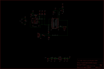
datalogger circuit

kidagain

New Member
My son and I, we want to control the temperature of a small green house by measuring the temperature in 3 different points and by let air in and out using a L293D driver to control a fan motor direction. Because it is our first experience with the datalogger, we would appreciate if you can review our circuit and advice.

Our first attempt was not successful, so, I think we need expert advice to define if the 255 value we got from the 24Lc16b, every time we read from it is because a faulty circuit.

Best regards
 

Attachments

techElder

Well-known member
You don't have pull-up resistors on the i2c lines at legs 14 & 15 of the 28X2.

Use 4K to 5K resistors to VCC.
 

fernando_g

Senior Member
Your 0V (ground) lines are waaaay too thin and waaaaaaaay too long, and routed in such a way that when the motors are started, they will induce noise on the Picaxe's ground line.

Please google "star grounding" for a proper way to lay out your ground paths on a PWB board.
 

johndk

Senior Member
I have found that when using DS18B20 in a "noisy" circuit it helps to place a 0.1uf capacitor between ground and Vcc right next to the sensor. It filters out the power supply noise nicely. In my particular case, I was getting 0 degree readings until I added the cap.
 

kidagain

New Member
Thank you for your answerss. We have, unsucsesfully, tried to improve our circuit, so we decide to go back to basic, and got all additionals off and left only the picaxe and the EEPROM, however we still got the 255 back. Would you please take a look to our programming and circuit.


Best regards

;---------------------------------------------------------
; Read the samples back to the terminal
;---------------------------------------------------------
hi2csetup i2cmaster, %101000000, i2cslow, i2cbyte
b0=10
main: hi2cout 0, (b0) ; Write data to eeprom
pause 20 ; Wait for write to complete

hi2cin 0, (b1) ; Read data from eeprom
'b1=b1-1
serout c.1,N2400, (#b1) ; Show result
serout c.1,N2400, (10,13)
pause 1000 ; Wait a short while
b0 = b0 + 1 ; Increment the data to write
goto main ; And repeat
 

Attachments

AllyCat

Senior Member
Hi,

The PCB layout pin numbers on the EPROM are incorrect (5 - 8 reversed). Also, your program code doesn't show any configuration to drive the Write Protect Pin (should be Leg 7) from PICaxe Leg 26 (B.5) ?

Cheers, Alan.
 

yv1hx

Member
kidagain

My 3 Cents to your problem:

1) Use CADSoft EAGLE as PCB Design Software, is very easy to use and there are Zillions of tutorials floating on the Net.
2) Some time ago I was playing with an EEPROM for storing a bunch of text LCD messages and save memory from the PicAXE for the main program use, attached is a image of my test circuit, I hope this can be useful for you.


3) Below is the crude piece of code used with the above mentioned setup.

Code:
' *****************************************************
symbol EEPROMscl = C.3		' 
symbol EEPROMsda = C.4		' 
' *** Variables ***
symbol MessageData = b3		; EEPROM data byte
;symbol xxxxxxx= b1		; RESERVED FOR FUTURE USE
symbol GPCounter = b5		' General purpose counter variable
' *****************************************************
' *** Directives ***
#picaxe 28x2			' specify processor
' #no_data				' save time downloading
#terminal off			' disable terminal window after downloading
#terminal 9600			' open terminal after download
setfreq m16				' Set processor speed
#com 4				' Set the download port
' *****************************************************
' *** Main Program ***
' *** LCD messages Table ***
'##########0000000000000000000000000000000000000000000000000000000000000000000000000000000000000000000000000000111111111111111111111111111111111111111111111111111111111111111111111111111111111111111111111111111122222222222222222222222222222222222222222222222222222222222222222222222222222222222222222222222222223333333333333333333333333333333333333333333333333333333333333333333333333333333333333333333333333333444444444444444444444444444444444444444444444444444444444444444444444444444444444444444444444444444455555555555555555555555555555555555555555555555555555555555555555555555555555555555555555555555555556666666666666666666666666666666666666666666666666666666666666666666666666666666666666666666666666666
'##########0000000000011111111122222222223333333333444444444455555555556666666666777777777788888888889999999999000000000011111111112222222222333333333344444444445555555555666666666677777777778888888888999999999900000000001111111111222222222233333333334444444444555555555566666666667777777777888888888899999999990000000000111111111122222222223333333333444444444455555555556666666666777777777788888888889999999999000000000011111111112222222222333333333344444444445555555555666666666677777777778888888888999999999900000000001111111111222222222233333333334444444444555555555566666666667777777777888888888899999999990000000000111111111122222222223333333333444444444455555555556666666666777777777788888888889999999999
'##########0123456789012345678901234567890123456789012345678901234567890123456789012345678901234567890123456789012345678901234567890123456789012345678901234567890123456789012345678901234567890123456789012345678901234567890123456789012345678901234567890123456789012345678901234567890123456789012345678901234567890123456789012345678901234567890123456789012345678901234567890123456789012345678901234567890123456789012345678901234567890123456789012345678901234567890123456789012345678901234567890123456789012345678901234567890123456789012345678901234567890123456789012345678901234567890123456789012345678901234567890123456789012345678901234567890123456789012345678901234567890123456789012345678901234567890123456789
table 0, ("Visualizador LCD     2 x 16     ")
;
GPCounter = 0
;do	; Uncomment this block to make sure i'm using the correct 28x2 pins
;	;pulsout EEPROMscl,1
;	;pause 20
;	pulsout EEPROMsda,1
;	pause 20
;loop
wait 10	; wait 10 seconds
gosub EEPROMWrite
wait 10	; wait 10 seconds
gosub EEPROMRead
end
' *****************************************************
EEPROMRead:
serout a.4, N9600_16, (cr, lf, "Mensaje:", cr, lf)
for GPCounter = 0 to 255
	i2cslave %10100000,  i2cfast_16, i2cword
	readi2c GPCounter, (MessageData)
	; serout a.4, N9600_16, (cr, lf,"GPCounter:",#GPCounter," EEPROM:",#MessageData, " (",MessageData,")") ;
	serout a.4, N9600_16, (MessageData)    ;
	pause 10
next GPCounter
pause 100
low EEPROMscl
low EEPROMsda
return
' *****************************************************
EEPROMWrite:
serout a.4, N9600_16, (cr,lf, "Programming ...")
; MessageData = "-" ; Write the "-" character to all memory locations
for GPCounter = 0 to 255
	i2cslave %10100000,  i2cfast_16, i2cword
	readtable GPCounter, MessageData     ' read text Characters in the Table
	writei2c GPCounter, (MessageData)
	pause 10
	; serout a.4, N9600_16, (cr,lf, "Writting EEPROM position:",#GPCounter, " with data: ",#MessageData, " (",MessageData,")") ;
next GPCounter
low EEPROMscl
low EEPROMsda
serout a.4, N9600_16, (cr, lf, "Programming done!",cr,lf) ;
return
good luck!
 

Attachments

kidagain

New Member
I want to thank you all for your info and guidance. To close the circle and leave some conclusion for those that may read this trail of notes in the future. By reading from your recommendation, I finally found my mistakes. I change from i2cslow to i2cfast. Add the small flap below to return to 10. Without it and because of my original layout I had to change from the programing to the controling conection db9 ports and always got at the point when picaxe got to 250 already (and keep there). From Marcos programming I discover that I could do call Hyperterminal from Picaxe code and I did it, as well as add a 180 k at the A.4 connection to the download port to use it as communication port as well.

I definitively don't have clear understanding of the 7 leg of the EEPROM. I found it connected to a picaxe leg, to 0V or to 5v. I ended up connecting it to 5v by a 4K7 resistance that worked well. I appreciate if you could explain this EPROM leg function?

if b0 = 250 then gosub adjust
goto main ; And repeat

adjust:
b0=10
return
 

inglewoodpete

Senior Member
Leg 7 on a 24Lc16b is a hardware write protect (WP) pin. It must be tied high or low in accordance with the 24Lc16b datasheet to allow/disallow data writing to occur.
 

hippy

Technical Support
Staff member
A little late but looking at the code in post #5 ...

hi2csetup i2cmaster, %101000000, i2cslow, i2cbyte

There are too many digits ( an extra trailing zero ) in the I2C Device Address.
 

yv1hx

Member
I want to thank you all for your info and guidance. To close the circle and leave some conclusion for those that may read this trail of notes in the future. By reading from your recommendation, I finally found my mistakes. I change from i2cslow to i2cfast. Add the small flap below to return to 10. Without it and because of my original layout I had to change from the programing to the controling conection db9 ports and always got at the point when picaxe got to 250 already (and keep there). From Marcos programming I discover that I could do call Hyperterminal from Picaxe code and I did it, as well as add a 180 k at the A.4 connection to the download port to use it as communication port as well.

I definitively don't have clear understanding of the 7 leg of the EEPROM. I found it connected to a picaxe leg, to 0V or to 5v. I ended up connecting it to 5v by a 4K7 resistance that worked well. I appreciate if you could explain this EPROM leg function?

if b0 = 250 then gosub adjust
goto main ; And repeat

adjust:
b0=10
return
I'm glad to helping you, best regards.
 
Top