6 VOLT 1Ah SLA Charging problem

ZOR

Senior Member
I am going to use a 6 volt 1Ah sealed SLA battery in a project. I have no experience of charging these batteries, looked around but many larger Ah units out there and 12v not 6.

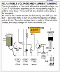
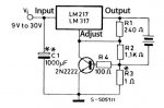
In looking I see people using the LM317 chip. I would ideally like the unit to top up the battery using an ADC pins monitoring on a 14M2.
At the moment I'm stuck, thinking maybe I should just have a socket for an external charger to plug in.

Trying to avoid a big bang, does anyone have a link to a suitable charger circuit.

Battery is Power Sonic PS-610 6 volt 1.0 Amp Hr.

http://www.ebay.co.uk/itm/6V-1AH-POWERSONIC-PS610-Rechargeable-Battery-for-UPS-toy-car-/201176691140?hash=item2ed710b1c4
 

ZOR

Senior Member
Thanks erco, would 500ma charge be damaging to this battery. I found a datasheet

http://www.power-sonic.co.uk/files/PS-610.pdf

It quotes initial charging current less than 0.25A. I looked through the forum site for discreet charging SLA batteries but could not find information on similar battery. Will keep looking as well as for external chargers. Regards
 

erco

Senior Member
500 mA is the max this unit will output, usually much less, especially if you don't drain your battery too deeply (not recommended for longevity anyway). This charger switches to float/trickle mode automatically, which is obviously a nice feature.
 

hippy

Technical Support
Staff member
You don't want to apply 500mA (0.5A) charge to that battery.

A safe charge rate is normally taken as "C/10" for most SLA, which for a 1Ah battery would be 0.1A.

As an SLA charges the current it draws will decrease, so I take the datasheet's "Initial Charging Current Less than 0.25A" to mean that's the maximum which should be applied.
 

ZOR

Senior Member
I don't know why, but I cannot find a commercial charger stating less than 300ma. I came accross this circuit, but would it be suitable if input voltage, zener, etc set for 7.2 volts @100ma. I don't want to kill the battery or have it explode using the wrong circuitry. I read that charger should start with constant current, then as nearly charged be put into constant voltage then a float condition. Don't think the circuit found does this, however all I want to simply do is charge the battery up, then with the Picaxe stop charging until the battery goes down to a certain voltage to kick off again.
CHARGERCIRCUIT.jpg
 

hippy

Technical Support
Staff member
Or you could just find a battery which suits C/10 = 500mA charging; eg 6V 5Ah, maybe even 6V 2Ah.
 

ZOR

Senior Member
Thanks hippy, I just bought these batteries on physical size to go in my box, any larger is a problem. I thought someone might have come in experienced with this problem in their project. Just find it crazy the manufacturer has nothing to offer with their battery other than specifications, and referring me to the dealer who does not have a suitable charger product. Maybe I will contact the manufacturers head office and get them more active.
 

BeanieBots

Moderator
Why do you want to cycle the battery like that?
You only get a few 100 cycles from a Lead Acid battery when it is used in cyclic manner.
Are you really after some form of battery backup?

Looking after a rechargeable battery (of any chemistry) is complex if you want it to last a long time but it can be very simple if you are not concerned about how long it will live.
As has already been described, for lead acid, you need to limit current until a certain voltage and then limit the voltage.
You can do that (although very inefficiently) by using two LM317s.
Configure one for constant current and use it to feed the second configured for constant voltage.
The issue that will cause debate is what current and what voltage they should be set for.
The answer will depend on what temperature the battery will experience, how quickly you want it to charge and how frequently you will be replacing the battery.
I float my AGM lead acid batteries at 13.8v and they last > 5 years when kept at normal domestic temperatures.
NEVER charge at > C/10 if you have any respect for your batteries.
 

ZOR

Senior Member
Thanks Beaniebots, you are right, I want the standby standard charge when required <0.25A and voltage 6.75-6.9v.

The suggested by Power Sonics dealer does not do a charger less than 300 milliamps. I have emailed Power Sonics USA and asked them. The battery will be inside a plastic box in the house, so normal house temp.
Does float mean having a constant low voltage on, ie in my case ~2 volts
 

BeanieBots

Moderator
"Float" is the voltage across the battery when it has been fully charged is standing by ready for use.
A 'good' charger will go through at least three stages during the charge process but for standby use, you are not so concerned about getting charge into the battery quickly or doing cell equalisation or desulfation or any other fancy maintenance.

If all you want is to have the battery ready for use and charge if it has been used, then the system I described will be fine.
You should set your 317 to have a voltage of 6.90v. (this will 'float' the battery at 6.90v)
If your power supply is a fixed voltage, you could simply use a resistor to limit the current INTO the regulator to 100mA.
If for example, your supply is 12v, then a 50 ohm resistor would limit the current to 100mA when the battery is at 6.9v
However, a totally 'flat' battery would be down at about 5.25v and the current would be over 100mA so the resistance should be about 63 ohms.
This would result in lower current available at the 'float' voltage making it take longer to charge but if that is not a problem then it makes things much easier.
I would suggest using 62 ohms which also happens to be a readily available value.
Use a resistor rated for at least 1W just in case the battery is ever very flat.
 

ZOR

Senior Member
Many thanks for your help Beaniebots. I just ordered some LM317T ic's for £1.98 for 5. As they are so cheap should I use 2, 1 being for fixed voltage, the other for current limiting.

I will not let the battery run down far, so it's just a top up I want as and when needed. Getting my fixed voltage of 6.9 volts is not a problem then, it's just looking how to set current limiting on the second 317. Presumeably this can only be adjusted when the battery is busy charging at 6.9 volts. Does the setting to 100ma remain the same throughout charging, being less and safe under the suggested 0.25A.

Really appreciate your help as nothing from Power Sonic.
 

BeanieBots

Moderator
That device looks ideal and a very good price for what it is.
It would be shame to use it for only 0.1A when it can deliver 5.0A!
Also, built-in DVM so you know what's going on.
All in all, almost too good to be true. (eBay - China - buyer beware)
Might try a couple out myself as they are so cheap.

Alternatively, as you already have some 317's, you could use one to limit the input current.
It will set the maximum current. Once the battery gets close to float voltage the current will drop off further until it equals the battery leakage current.
The circuit is simple, just the 317 and a single resistor. Loads of examples out there, this is just one
http://users.telenet.be/davshomepage/current-source.htm
Just put it in series with the input to your 317 voltage regulator.

The circuit on page 13 of the file linked by Flenser would be just as good.
There are many ways to do it. The choice is yours and it is often based on what you have to hand.
 

BeanieBots

Moderator
That device is a bit more appropriate for the levels you are working at.
I've used similar modules using the same switcher chip. It's a good solid work-horse though a little out-dated these days.

I've just checked the website and the schematic comes up fine for me.
 

ZOR

Senior Member
Thanks again Beaniebots. I use adblock in my firefox browser and that stopped the images appearing on the website, got them all now.
I will play with the 317's when they arrive, knowing much more with the help given, and try the other items on arrival from China. At least I can move along now, thanks again, have a good weekend
 

Flenser

Senior Member
This module you ordered http://www.ebay.co.uk/itm/201310245111 looks like it will do exactly what you want.

What BeanieBots and I have been suggesting are circuits to create a simple two stage SLA charger using the LM317 to limit the max current and the max voltage. The module you ordered appears to do exactly this, as you probably have already seen from the section in the ebay listing that describes how to use the module to charge a battery. Your module has the added advantage of being cheaper than we could probably make a LM317 charger by buying the individual components, comes on a small neat PCB and doesn't require any work to construct. This is a good pick-up on your part.

Another suggestion I have is to run this module using something like a 9V plugpack, if you can. The lower the voltage you can run it from the less voltage that has to be dropped by the module and the cooler the module will run.
 

ZOR

Senior Member
Many thanks Flenser. Yes I am going to use 9v input for reasons as you say, to reduce heat with the device in lowering the final required voltage, in addition getting nearer to 5 volts for the Picaxe. I will have to suck it and see if it will cause problems with the Picaxe supply. I will use some large capacitors and decoupling, otherwise run a seperate supply. But thanks to you and Beaniebots for the help, once I knew I had to get a fixed voltage/current it led me on the trail for the Ebay items.

Have a good weekend, Regards
 

AllyCat

Senior Member
Hi,

That looks to be a switched-mode (PWM) power regulator, so dissipation should be quite low, regeardless of the supply voltage (provided it's high enough).

If you were in a hurry, the LM317, Fig 13 circuit linked in post #15 should be fine, probably with R3 = 5.6 ohms and R2 = 2k2 pot (wiper linked to one end).

Cheers, Alan.
 

ZOR

Senior Member
Thanks Alan. I should get the LM317T early next week, the other items are coming from China, so I have time to play. Are your resistor values based on 9 volts input?
That taking care of the current and just needing 9 volt fixed input voltage I should be there as an alternative. Regards
 

AllyCat

Senior Member
Hi,

The resistor values would be the same for an input of 9v or 12v, or even higher. The only thing that would change is the heat dissipated (wasted energy) inside the regulator.

The 5.6 ohms (R3) sets the maximum current at just over 100 mA (transistor Vbe is about 600 mV) and the ratio of R2 : R1 sets the output voltage. As you need 6.9 volts, it would probably be possible to calculate/find two fixed resistors to get quite close, but using a pot allows you to get it "exactly" correct, even if you have only 220 or 270 ohms, etc. to hand for R1.

Cheers, Alan.
 

ZOR

Senior Member
Many thanks Alan, that's perfect. I did not realise the circuit would take care for both voltage and current. Will definately have a go with the LM317T's when they arrive.
Regards
 

ZOR

Senior Member
Still waiting bits to come for my tests with LM317.
However looking ahead at using the circuit below, I know with the Picaxe I can monitor the batteries voltage being low or charged, but questioning how I can incorporate the circuit in as a stanby one. It does not have a common ground, should I use steering diodes from it's output to the battery so my battery can be in place to the Picaxe if power failed. ???

LM317CHARGER.jpg
 

techElder

Well-known member
Looking at the "big picture", I think you may have eliminated many solutions from the very start with this statement ... "I am going to use a 6 volt 1Ah sealed SLA battery in a project."
 

ZOR

Senior Member
Yes correct, as a standby supply. Forgot to add I do not envisage putting 6 volts into the Picaxe, it will get finally dropped.
 

AllyCat

Senior Member
Hi,

It does not have a common ground, should I use steering diodes from it's output to the battery
Probably not.

That circuit diagram is shown from the point of view as a "battery charger" (power supply) with the battery "floating", so the Earth is shown on the power supply side.

However, in your case, the battery is the effective (normal) power supply (for the PICaxe, etc.), so the negative side of the battery should be considered as "Earth". This means that the output from the mains adapter needs to be floating, but that should be the case with almost any "wall wart", which generally now have a plastic (insulating) "earth" pin (or none at all).

Cheers, Alan.
 

ZOR

Senior Member
Thanks Alan, that's fine then, takes the problem away. Should have my bits soon so I can play with 317. Just ran a battery down a bit to work with. Regards
 

ZOR

Senior Member
All the bits came. Used values
The 5.6 ohms (R3) sets the maximum current at just over 100 mA (transistor Vbe is about 600 mV) and the ratio of R2 : R1 sets the output voltage. As you need 6.9 volts, it would probably be possible to calculate/find two fixed resistors to get quite close, but using a pot allows you to get it "exactly" correct, even if you have only 220 or 270 ohms, etc. to hand for R1.
However test with no load on output gave between 7.25 and 7.7 volts with 9 volts input. I tried reducing R1 value, got down to 10 ohms but resistor got very hot.
I ended up changing the 2k2 pot to a 1k resistor, leaving R1 at 240 ohms, and leaving R3 at 5.6 ohms. With 8.45 volts going into the vircuit I get 6.90 volts out. An input of 9 volts gives me 7.47 volts out, and at 12 volts in I get 10.48 volts out no over heating.

In playing around with R1 AND R2, don't know how this is effecting 100ma max current. Any ideas of direction please, thanks
 

ZOR

Senior Member
I am so stupid. I had not used the correct pin in my breadboard, 1 pin out, so the 317 adjust pin was not connected. Red face, gone back to test!
 

AllyCat

Senior Member
Hi,

It's the RATIO of R2 : R1 which controls the output VOLTAGE. It should not directly affect the output current (which is controlled by R3).

Are you saying that the full trange of the Pot gave only an output range of 7.25 to 7.7 volts? It should give a full range of almost the input voltage down to about a volt.

Reducing R1 should INCREASE the output voltage, but it still shouldn't get hot so a connection/component fault is indicated (and your 10.48v output suggests that it doesn't appear to be regulating at all).

It would be wise to add a small dummy load (i.e. not open circuit) of perhaps 1k for testing, but the divider chain (R1 + R2) should be giving that anyway.

Cheers, Alan.
 

ZOR

Senior Member
Hello Alan, I think your message came up as mine was. I picked the wrong bit on the breadboard leaving the 317 adjust pin not connected. I corrected it and it all works perfectly just as you had said. So I am very pleased it's ready to use. Thanks for the clarification of which part was current and voltage. Excellent thanks for all your help.
 

ZOR

Senior Member
I want to put 12 volts into the input of the LM317 when the battery needs charging. I don't want a relay, and although never working with Mosfets before, I guess if the Picaxe could control the gate, and the Mosfet could deliver my 12 volts to the 317 it would be good. However would it be an N channel or a P Channel I would need?. I am playing with an N channel at the moment but having to put a resistor from the drain to 12 volts, and getting my 12 volts from before the resistor, ie on the drain pin. Is this correct or should it be a P channel device? Thanks (using IRF2807N)
 

techElder

Well-known member
To do that, you need a "high side switch" which in your case as described would be a P-channel.

... but then that in itself brings up more questions needing answers.
 

ZOR

Senior Member
Many thanks, thought that might be the case but didn't have one to play with. Regards
 

lbenson

Senior Member
Can you not put the N-Channel mosfet on the 0V pin of the LM317? Below the 2n2222 if you're using figure 13?
 

AllyCat

Senior Member
Hi,

I want to put 12 volts into the input of the LM317 when the battery needs charging.
I don't understand, what is the intended purpose of the FET? Is the "12 volts" in place of your original 9 volts, or some kind of alternative supply?

In principle you could use either a P-channel or N-channel FET. The P-channel would act like a (relay) switch, or the N-channel as a "source follower" which could take some of the (extra) power dissipation away from the LM317 (BTW which package are you using? ). But in either case you also will need a low power NPN transistor to tolerate/interface to the 12 volt rail (which a PICaxe pin can't do).

But if you just want to switch off/on the charging, that can be done by "fooling" the LM317 that the maximum current or voltage has been reached (by injecting a current into the transistor or voltage divider chain).

Cheers, Alan.
 

ZOR

Senior Member
Thanks Ibenson, 317 circuit below Thanks Alan, I found your resistor values all worked for 9 and 12 volts with the preset for setting voltage.
Basically I am trying to avoid using a relay to put a voltage on the input of the 317 when the battery needs topping up. I was trying to find a component way of doing it.
Below is a ROUGH circuit of what I am trying to do. Unfortunately I have not got to grips on editing/copying component templates but will try to explain.

PIRBOXPOWER.jpg

D1 and D2 are to stop the battery discharging during standby through R1 and R2. I show an N channel Mosfet (never used Mosfets before) which was to be putting a voltage into the 317 when the gate had input from the Picaxe monitoring the battery. However this does not work or would supply a high enough voltage into the 317 so thought it should have had source tied to 9v or 12v and been given TTL input from Picaxe.

The dc adaptor for the unit maybe 9 or 12 volts, undecided at present. Both output from battery and the dc adaptor end up via the 2 diodes in Hi 1 to a linear stabilizer to get my 5 volts to the Picaxe.

Hope this does not confuse you, as said the circuit is only a rough guide. My battery gives 6.4 volts, the diode will drop it further, and I will need headroom to reduce/control to 5 volts, so an alternative final end has to be derived.

The problem for now is just to avoid using a relay. Regards

EDIT Sorry, cannot remove incorrect circuit below, don't know why?
 

Attachments

Last edited:
Top