Self Power PICAXE Question

bpowell

Senior Member
So, I've been looking at the circuit diagrams...and I have a question.

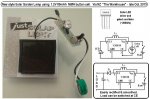
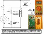
Most of the self-powered PICAXE circuits (where a momentary switch powers up the PICAXE, and then the PICAXE itself holds a transistor "on" to maintain power...) show two transistors...the PICAXE drives and NPN which in turn, drives a PNP which supplies the power to the PICAXE.

It seems like this could be done with a single transistor...an NPN on the GROUND side of the PICAXE...and having the momentary switch being on the ground side of the circuit vs the positive...is this possible?

As I type this, I'm wondering if there are concerns with the PICAXE powering itself via a different path if the positive is always "hot"...allowing the PICAXE to power through one of the other pins?

Also, would a single NPN on the negative rail result in the PICAXE being at a different ground potential than the rest of the circuit given the CE Saturation voltage?

I think I'm answering my own questions here, but would like some input.

I'm building a little light circuit that I would like to have turn itself off after 30 minutes.

Thanks everybody!
 

AllyCat

Senior Member
Hi,

If the "earth" rail (Vss) of the PICaxe is up at the supply rail (Vdd) potential, how does it NOT drive current into the NPN base? Note that EVERY PICaxe pin has a diode which connects it to the substrate (Vss).

But there's no need to remove power from the PICaxe, if it's put to "sleep" properly. Its current drain need be no more than the collector leakage through the NPN that you're trying to use as a switch.

Cheers, Alan.
 

bpowell

Senior Member
Hi,

If the "earth" rail (Vss) of the PICaxe is up at the supply rail (Vdd) potential, how does it NOT drive current into the NPN base?
Hmmm...I'm not explaining correctly...I was thinking having Vss connected to the colleecter of the NPN....the emitter connected to GND, and the momentary switch providing GND to VSS on the PICaxe until it can turn the NPN on, which would keep the connection to ground available for the PICaxe. I wasn't planning to have Vss at Vdd potential...my fault for not explaining a little more clearly.

The two-transistor solution with the switching on the Vdd side "feels" right...I'm just trying to wrap my head around it.

As for "Sleep mode"...as I started looking at my schematics...I realized I need to supply (and remove) power (8.4V) from a 5V LDO regulator...not from the PICAXE itself...no point in keeping the regulator running if I want the circuit to be "off"...so I'm thinking the 2-Transistor solution is the way to go.
 

techElder

Well-known member
bpowell, the PICAXE can't properly operate with its ground connection at the collector voltage of an NPN transistor ... and for other reasons, too.
 

bpowell

Senior Member
Hi IWP...I was thinking of connecting the base of the NPN to a pin on the PICAXE...drive it high to turn the transistor on...allowing a "short" between Vss and GND.
 

bpowell

Senior Member
bpowell, the PICAXE can't properly operate with its ground connection at the collector voltage of an NPN transistor ... and for other reasons, too.
Yeah, I think there would be a difference in ground potential between the Vss and the rest of the circuit....well, it helped just typing it out. Thanks!
 

AllyCat

Senior Member
Hi,

IMHO the saturation voltage (C-E) when the transistor is ON is unlikely to be a problem. The issue is how (and what happens when) you try to turn the NPN OFF (i.e. what happens to the collector voltage?).

However, the main issue now appears to be how to turn the supply regulator off. There are some ultra low power consuming regulators, or you might find one with an "enable" input pin.

Cheers, Alan.
 

KMoffett

Senior Member
There is a leakage path problem with the attempt to do low side switching the power off. When you try to lift the Picaxe Vss from the negative supply there is a leakage path out through the I/O to the base (or Gate) of the switching transistor. Been there...tried that...posted the result :(

Ken

Ken
 

AllyCat

Senior Member
Hi,

It's not just a "leakage" path (which might be overcome by a suitable pull-down resistor) it's a forward conducting diode which feeds current from Vss out through any I/O pin (and cannot be overcome).

Cheers, Alan.
 

dave finney

New Member
there's no need to remove power from the PICaxe, if it's put to "sleep" properly. Its current drain need be no more than the collector leakage through the NPN that you're trying to use as a switch.

Cheers, Alan.
I was thinking of using the 2 transistor (+ 2 resistors) method to switch device off (with switch-on by push button).
This will reduce current when off to close to zero but it might be a better solution to put the PICaxe to sleep as suggested above.

Does anyone know:
1) how can the PICaxe be put to sleep and woken up?
2) what current will be consumed in "sleep"?

This is a possibility:
================

disablebod ; disable brown out
let wakeup = 0
do:
sleep 1 ; sleep for 1 unit of 2.3 seconds (2.3x1)
if pinC.0 = 1 then let wakeup = 1
loop until wakeup = 1
enablebod ; enable brown out

================
Note: The disablebod and enablebod are not required but they reduce current in sleep.

Obviously that's not very good because the PIC is woken up every 2.3 seconds and the button may have to be pressed for up to 2.3 seconds.

What's the correct way to do it.
 

srnet

Senior Member
Obviously that's not very good because the PIC is woken up every 2.3 seconds and the button may have to be pressed for up to 2.3 seconds.
What's the correct way to do it.
You can put the PICAXE to sleep permanently with 'sleep 0'

Then you need some external means, such as a switch, to wake it up.
 

dave finney

New Member
You can put the PICAXE to sleep permanently with 'sleep 0'

Then you need some external means, such as a switch, to wake it up.
Thank you but I see 2 problems using an 18M2.

1) the manual says "On non-X2 parts the command ‘sleep 0’ is ignored."
2) how do you wake it up?

PE allows 'sleep 0’, but I've not tried it in the 18M2.
Is there a pin that needs a voltage to wake up, is that set in the program?
 

manuka

Senior Member
I'm building a little light circuit that I would like to have turn itself off after 30 minutes
bpowell: Just how beefy is your "little light circuit" ? How sharp a cutoff time do you need ? Budget?

Far be it that I should mention non PICAXE approaches, BUT for simple needs perhaps this 2N7000 based "FETlington" DMM auto power off may do- check specific details from Step 10.

Consider also using a 4 leg YX8018 "quadistor" from cheap SGL (solar garden lamps). Load circuitry is easily controlled at their CE leg. Normally even a smidgeon of PV input at this terminal will switch off the LED of course. Numerous web sites outline hacks using the YX8018 from these lamps - Google.

Extra: FWIW -a new NiMH button cell style SGL has just arrived here in NZ (pictured) & they sell for ~US$1 each = worth gutting it just for parts?! In spite of the smaller 80mAh battery the LED stays on a good 8 hours when fully charged. The PV (25mm x 26mm) produces 10-20mA in bright sun. When removed from the lamp housing the components pictured weigh ~8 grams. Stan.
 

Attachments

Last edited:

dave finney

New Member
It seems that "SETINT" might be the key.
Here is a quick idea for a sub that switches off the PICAXE (sleep).
To wake up, take pinC.0 to ground.

======
gosub switchoff

switchoff:
let on = 0
disablebod ; disable brown out
setint %00000000,%00000001 ; activate interrupt when pinC.0 goes low

do
sleep 65535 ; sleep for 150,730 seconds (2.3x65535) or 41.8 hour
loop until on = 1 ; leave if interrupt is activated
enablebod ; enable brown out
return

interrupt:
let on = 1
return
======

Don't know if that'll work, but along those lines might work.
How much current might the PICAXE use in sleep?
 

AllyCat

Senior Member
Hi Dave,

Not with an M2 because the interrupts are only polled (between instructions), so are not executed in Sleep.

Current drain in Sleep depends on which functions remain active and the temperature, etc.. It can be assumed to be less than 50 uA (maybe much less) but there is considerable detail in sections 30 and 31 of the Microchip base PIC data sheet on this page.

Your design may depend on how rapidly you want the pushbutton to wake up the chip. The PICaxe only needs to wake up for a few ms to check the switch and you might "stretch" the button press using the Set-Reset Latch, or simply a capacitor. Another posibility is to reset the PICaxe, either by interrupting the supply or taking the Serin Pin briefly high (as if starting a new download), perhaps with a "status" flag in EEPROM to indicate that it's a "wake up" and not a new download / run.

Cheers, Alan.
 

dave finney

New Member
Thanks Alan,
I suspect someone has worked out a really good way to put the PICAXE into a really low power state, and then wake it up, but it seems the best I have now is something like:

This will wait until the button is released, then sleeps waking every 2.3s to check if button is pressed.

gosub switchoff

switchoff:
do
loop until pinC.0 = 1
disablebod ; disable brown out
do
sleep 1 ; sleep for 1 unit of 2.3 seconds (2.3x1)
loop until pinC.0 = 0
enablebod ; enable brown out

I suspect I'll end up using the 2 transistor (+ 2 resistors) method to switch off, seems more secure!
 

dave finney

New Member
In battery powered operation, it would be useful to know the supply voltage. This could then be displayed on the OLED.

Could anyone tell me how this is done?
 

dave finney

New Member
Thanks Alan, most useful.

have used this from your 2nd link:

calibadc10 word_up
word_up = 52500 / word_up * 2
bintoascii word_up,code3,code2,code1

It gives battery voltage in 20mV steps displayed on OLED, eg: "4.12v".
 
Top