Hi,
Following on from this recent thread I was wondering if it is possible to arrange for the DVM digits to exactly correspond to the 256 levels from a variable byte. Theory suggested that it should be possible (with a reasonable quality DVM and good design) but all my practical attempts, even with careful coding, just didn't quite make it. Like in the original post, I used PWMOUT because I find the PWMDUTY command rather greedy of program code space.
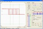
It was only when I went back to the fundamentals, directly altering the PWM values, that I noticed certain changes didn't affect the output value at all (average analogue level and ultimately the pulse width itself). The attached code and 'scope waveform should indicate what is (or isn't) happening. It's not easy to show in a single screenshot, but the faint traces are the falling edges from the PWMDUTY pulses and the bold lines show the PWMOUT pulses. The vertical green cursors indicate the expected range from 10 to 20 (and correspond to the actual extent of the PWMDUTY pulses).
Looking at the Microchip base PICaxe data sheet it can be seen what's happened. The two LSBs of the 10-bit word are stored in a separate (the Command) register and the higher of these two bits appears to have got "lost" (always 0). I haven't checked any other pins, or other PICaxe versions, as I feel I've already wasted more than enough time looking for non-existent errors in my original code.
Cheers, Alan.
Following on from this recent thread I was wondering if it is possible to arrange for the DVM digits to exactly correspond to the 256 levels from a variable byte. Theory suggested that it should be possible (with a reasonable quality DVM and good design) but all my practical attempts, even with careful coding, just didn't quite make it. Like in the original post, I used PWMOUT because I find the PWMDUTY command rather greedy of program code space.
It was only when I went back to the fundamentals, directly altering the PWM values, that I noticed certain changes didn't affect the output value at all (average analogue level and ultimately the pulse width itself). The attached code and 'scope waveform should indicate what is (or isn't) happening. It's not easy to show in a single screenshot, but the faint traces are the falling edges from the PWMDUTY pulses and the bold lines show the PWMOUT pulses. The vertical green cursors indicate the expected range from 10 to 20 (and correspond to the actual extent of the PWMDUTY pulses).
Looking at the Microchip base PICaxe data sheet it can be seen what's happened. The two LSBs of the 10-bit word are stored in a separate (the Command) register and the higher of these two bits appears to have got "lost" (always 0). I haven't checked any other pins, or other PICaxe versions, as I feel I've already wasted more than enough time looking for non-existent errors in my original code.
Rich (BB code):
; Test code to show apparent 20M2 PWMOUT bug.  AllyCat,  August 2015.
#picaxe 20m2
#no_data
#terminal 4800
do
   for w0 = 10 to 20
      pwmout PWMDIV64,b.1,255,w0
      pause 1000
   next
   pwmout b.1,off
   sertxd("PWMDUTY",cr,lf)
   pause 5000
   pwmout PWMDIV64,b.1,255,0
   for w0 = 10 to 20
      pwmduty b.1,w0
      pause 1000
   next
   sertxd("PWMOUT",cr,lf)
   pwmout b.1,off
   pause 5000
loop
Cheers, Alan.
Last edited: