[Help a Beginner] Wake-up light program start problem

Crossditch

New Member
Greetings!

I'm looking for some help with a project of mine. I've been working on my first picaxe project: a simple wake-up light that consists of a regular alarm clock, 08M2 board, power led driver and the power led light unit. The idea is that the alarm signal from the clock would start a picaxe program that will send PWM signal to the power led driver, and so slowly light up the leds. An artificial sunrise.

I managed to figure out a program for lighting the leds with PWM. The problem, however, lies with triggering the program with the alarm. I figured I'd just remove the alarm clock buzzer and connect the wires to an input on the picaxe board, and then just use
Code:
 main:		if pinC.4 = 1 then goto light
		pause 100
		goto main
The "light" (PWM) program starts running as soon as the pic board is powered, regardless of the alarm being on or off. It seems to be high all the time. With the buzzer the alarm clock works as it should; voltage across the buzzer is 0 when alarm is off, when it goes on, the voltage varies between 0,3-1 V (measured with multimeter).

Reading the analog value of the alarm input pin shows decimal values varying between 60-255, again with the actual alarm not seeming to affect the value. (What exactly does this value even tell me? Why not just a simple voltage? :confused: ) I hoped I'd get different values when the alarm goes on so I could use something like if b1 > 100 then light .

My own (rather uneducated) guess is that the alarm clock has a switch on the ground side of the buzzer, and when connected to the picaxe it leaks through the picaxe input to the picaxe ground and thus is high all the time. Is that even possible, or am I completely lost? The alarm clock has its own 1,5V battery, while the Pic works on 4,5V (3xAA)... The led driver and leds have their own power source (old laptop power supply). Yeah, it's not too sophisticated, because I'm still learning the basics.

Can anyone confirm whether my diagnosis might be wrong or right, how would I tackle it if it's right and what would be the cause if I'm mistaken, and how would I deal with it?
Any help will be greatly appreciated. I'd love to get this thing working, it might make having to wake up way too early a bit easier.
 

rossko57

Senior Member
When you say connected the ex-buzzer wires to your Picaxe, two wires presumably with one to pin C.4, where does the other go exactly?

The inactive buzzer output might be "floating" as you have guessed, the workaround would be a pulldown or pullup resistor. An in-series resistor as well would be a smart idea, to protect the Picaxe input.

When activated, the buzzer might be switched at audio frequency and/or pulsed to produce bip-bip-bip. That's probably not going to be a problem if you are only looking for a one-shot trigger.
 

hippy

Technical Support
Staff member
Welcome to the PICAXE forum.

The main problem is that you don't really know the nature of the circuit you are trying to tap into. It may well be pulsed as roskko57 suggests and it could also be using some push-pull buffering to attain a decent volume from a low battery supply, may even be floating in some way with respect to the rest of the circuit.

The best course would be to try and reverse engineer the circuit, taking it apart and tracing the component tracking, seeing where things go, what the buzzer connects to.

An oscilloscope on the buzzer pins may reveal more about the signal if you have access to one.
 

Crossditch

New Member
When you say connected the ex-buzzer wires to your Picaxe, two wires presumably with one to pin C.4, where does the other go exactly?

The inactive buzzer output might be "floating" as you have guessed, the workaround would be a pulldown or pullup resistor. An in-series resistor as well would be a smart idea, to protect the Picaxe input.

When activated, the buzzer might be switched at audio frequency and/or pulsed to produce bip-bip-bip. That's probably not going to be a problem if you are only looking for a one-shot trigger.
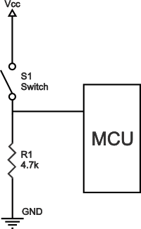
The other wire goes to the same pin. I figured the picaxe would pick up the passing signal. I did try with a pull-down resistor, like this:

Without the switch though, as the alarm clock is supposed to do the switching. I imagine the problem might well be something as stupid as the other wire going to wrong place, as I've had none to teach me even the basics. Yeah, one can self-educate, but to a beginner much of the information is too deep and complicated, and often a lot of existing knowledge is expected.

I'd guess the alarm signal is pulsed, as it produces the bip-bip-bip noise. Its voltage seems to pulsate when checked with the multimeter, and when tested with the picaxe debug, the analog value pulsates as well. I'm going for just a simple one-shot trigger, for now at least.

The in-series resistor would be placed between the signal wire and the picaxe input, right? That'd be a rather small value resistor, I assume?

Welcome to the PICAXE forum.

The main problem is that you don't really know the nature of the circuit you are trying to tap into. It may well be pulsed as roskko57 suggests and it could also be using some push-pull buffering to attain a decent volume from a low battery supply, may even be floating in some way with respect to the rest of the circuit.

The best course would be to try and reverse engineer the circuit, taking it apart and tracing the component tracking, seeing where things go, what the buzzer connects to.

An oscilloscope on the buzzer pins may reveal more about the signal if you have access to one.
My bet is the clock is about as simple as those things go. It was rather cheap. I'd look for another clock, but I've already built a new pretty wooden body for this exact clockwork. I'd also rather not open the thing, as the last clockwork I opened scattered its little parts all over the place :p Don't expect I'd learn much of its insides by myself, anyway. The picaxe shouldn't mind if the signal pulsates, if it just goes over the high threshold even once? I recall reading somewhere the Pic isn't too picky about signals. And all it needs to do is to detect the alarm signal once to start the light program. Now it seems to detect a signal even when the alarm is off.

I'd put an opto-isolator on that output from the clock. Will solve most of the problems that you will encounter.

DATASHEET: MCT6, MCT61, MCT62 FAIRCHILD (PDF)

MOUSER: http://www.mouser.com/ProductDetail/Fairchild-Semiconductor/MCT6/?qs=sGAEpiMZZMteimceiIVCB4Jy96LwY5d2Y49m8MiFvgg=
After reading a bit about these opto-isolators, I think I roughly understand how they work, but not quite what exactly they would do in this setup of mine. An opto-isolator might be the answer, I've no idea, but first and foremost I'd like to understand what is the problem.


Thank you all for taking the time to reply.
 

rossko57

Senior Member
The other wire goes to the same pin.
Umm, if you have two wires going to the same place, there is no possibility of a signal inbetween them.
The Picaxe input is looking for the voltage at the pin. "Voltage" of course has no meaning unless it is with reference to something else - conventionally that'll be referenced to 0v / ground / earth.
In a simple case, where you are trying to pass a signal between two bits of equipment, you would link their 0v / ground references. That's what the second wire is for?

You may or may not have that simple case though. Some easy direct connection might be viable. Or might not, the buzzer could be powered with a 24V audio signal, you'd see little on your multimeter but that would soon smoke the Picaxe. Optocoupler is a sound recommendation.
 

Crossditch

New Member
Umm, if you have two wires going to the same place, there is no possibility of a signal inbetween them.
The Picaxe input is looking for the voltage at the pin. "Voltage" of course has no meaning unless it is with reference to something else - conventionally that'll be referenced to 0v / ground / earth.
In a simple case, where you are trying to pass a signal between two bits of equipment, you would link their 0v / ground references. That's what the second wire is for?

You may or may not have that simple case though. Some easy direct connection might be viable. Or might not, the buzzer could be powered with a 24V audio signal, you'd see little on your multimeter but that would soon smoke the Picaxe. Optocoupler is a sound recommendation.
I see. So, in a simple case, I should have the ex-buzzer positive wire going to the picaxe pin through an in-series resistor, and the ex-buzzer ground wire connected to the picaxe board ground? There's no problem with connecting the grounds of two different battery power sources? In such case, does it matter if the alarm signal switch on the alarm clock is between the ex-buzzer negative and battery negative? There is continuity between the buzzer (+) and the battery (+) all the time, but between buzzer (-) and battery (-) only during the alarm.


When using an optocoupler, I would connect the ex-buzzer wires to the optocouper's cathode and anode, and the picaxe board V+ to the optocoupler collector and the emitter to the picaxe input pin (and to picaxe board ground through a pull-down resistor?), right? I've access locally to a couple of optocouplers: CNY17F-2, LTV827, 4N25 and 4N35. Perhaps the CNY17F-2 would work?
 

techElder

Well-known member
The optocoupler gives you the opportunity to tailor the output to your PICAXE power supply. Ground the emitter side of the output transistor and put a 10K - 100K from the collector to the PICAXE power supply positive. Your output is the collector.

When there is current in the input circuit, the output goes to a LOW condition.

So, how do you get current to flow in the input circuit? Wire the input in SERIES with the "buzzer" circuit. CAUTION! Think first.

The input is an LED. It has two parameters that you have to be careful with; current and reverse voltage.

The reverse voltage on the optocoupler that you chose is about 6 volts. It should be happy with about 10 mAmps turning it on.

Hippy's comments in #3 above are very pertinent. Until you can specify what your buzzer output is, no one can really help much more than guessing what it is.

CAUTION! Or ... you can just throw something in the circuit and see what happens! Let the magic smoke out! Be free! Run naked in the wind! ;)
 

Crossditch

New Member
I threw caution out of the window, and ran free and naked with the wind to the local electronics store, grabbed the CNY17F-2 optocoupler and a testing board. I set the thing up and was prepared for a glorious success, but no. Not even smoke. The emitter and collector would not turn conducting. A small led in the place of the buzzer wouldn't light either. Testing with the multimeter showed voltage going up to 0.4V at most. I assume there's not enough power to light the led in the optocoupler..? The optocoupler conducts when powered with 4.5V, but not with the buzzer signal.

I've no idea how I'd further specify the buzzer output. I've no access to an oscilloscope (not that I'd know how to use one, either) and I don't think I could tell anything by opening the clockwork.

Any thoughts? Maybe I ought to give up with this clock and try to get a differrent one?
 

premelec

Senior Member
Please post an actual picture of your 'buzzer' and any wires to it when it IS operating in it's original use... that should help us see what the problem may be...
 

techElder

Well-known member
All is not lost! You are now much more educated than you were early on!

See post #11 ... :)

PS. Put your clothes back on ... the neighbors are talking!
 

Crossditch

New Member
I took some pics so I might be educated further:

The clockwork is originally from a cheap alarm clock I disassembled. I changed the original wires, the alarm switch and the battery holder. On the clockwork there are 5 terminals where the wires are soldered to:
1. Two wires; battery(+) and buzzer(+)
2. Battery(-)
3. Buzzer (-)
4. Alarm on/off switch
5. Alarm on/off switch

And here's a closer look at the buzzer. Didn't solder it back onto the wires for the photos. There's two terminals on the bottom, one marked (+) and the other surprisingly (-). On the top there are two marks on the other sides of the hole in the middle; a + in a circle and the letter J (I think..) A bit over 8mm high and tad under 12mm wide, not much more to tell about it.


PS. The neighbors were screaming.
 

rossko57

Senior Member
Clockwork? I think this could prove very simple. Remove the battery, test with a meter for continuity between clock terminals 2 & 3, while messing with the alarm time setting. I guess you will find this to be a simple switch, activated by the mechanical clock.
Any reason you can't disconnect and throw away battery holder, buzzer, on/off switch ... and just use the clock contacts wired directly to your Picaxe as a switch, like you previously illustrated?
Is it really clockwork, or battery driven? We can still come up with a simple scheme if battery driven.
 

Crossditch

New Member
It's battery driven. Pardon if some of the terms I use are misleading, as English is not my native language. When the alarm switch is off, there is no continuity between 2 and 3. While the alarm switch is on, and the clock is turned manually past the alarm hand (there's an audible "click" when the alarm is triggered) there is a weak continuity. The multimeter doesn't do the continuity beep, but I can't seem to get a proper reading of the resistance for some reason. Maybe the circuit puzzles the multimeter.

Well, the clock and the picaxe have their own batteries (1,5V and 4,5V) because I though it'd be the most simple way to supply them with the power they desire. It would admittedly seem more sophisticated if they shared a power source instead. The buzzer was going to be thrown away, as there's no need for a nasty beeps, only a start signal for the lighting program. The outside on/off alarm switch is required to turn to alarm on and off, naturally.
 

premelec

Senior Member
Note that you likely need a level shifter as the clock runs on 1.3 volts - or down to 1 volt likely. This could be a signal into a BJT NPN base with it's collector connected to resistor to V+ of PICAXE. Not enough to drive an optocoupler directly. As rossko57 says you can likely use the 'click' contacts of the clock mechanism.
 

Crossditch

New Member
Heh, I need to do some googling after pretty much each comment to understand them. Is the level shifter used to turn the weak clock signal to a higher voltage signal for the picaxe? As you might guess, that's one more component I've never even heard of.

I took the clock apart. I think I found all them little gears which popped out... Here's a pic of the clock's insides (without the little gears and plastic gear holder frame blocking the view)


And I expected this to be a simple case of just soldering the buzzer wires to the picaxe. :rolleyes:
 

premelec

Senior Member
It's so simple... indeed... maybe... have you located the alarm mechanical switch contact? It looks from your picture above one of the mechanical switch contract is the lower solder pad connecting into the metal on a gear. If you can isolate that switch it can be used to switch a PICAXE pin. Since you are using 2 voltages - 1.4 & 4.5 you could choose to derive the 1.4volts from the 4.5v source or stay with the 1.4v battery. The clock and PICAXE both run on low currents so a simple resistor divider could supply clock voltage from 4.5 v... perhaps with a capacitor added across the clock to allow a bit of current kick on the clock pulse.
 

Crossditch

New Member
It's a very simple mechanical switch. The battery (-) (terminal 2) is connected to the metal switch frame through the yellow wire. When the switch closes the signal passes to the alarm on/off switch (terminals 4 & 5) and through it to under the black blob. Then something mysterious happens inside the mysterious black blob, and the minimal current is pulsated to the buzzer on terminal 3. There also seems to be a small bridge (marked with the red circle) from the mechanical switch to the strange black blob.


I guess the switch could be isolated completely from the clock by removing the yellow wire and the wire from the on/off switch (terminal 4) and probably scraping off the bridge marked with the red circle(?).

The two switches in series (alarm on/off switch and the clock alarm switch) could be then connected to the picaxe board like this:

(with the switches being in the place of the S1 switch in the pic)

Perhaps I'll just let the clock have its own battery. That way it'll work as a simple clock with just one battery when the alarm is not needed.

Does that seem like a decent plan? Just making sure before I get to work and mess something up :p
 

techElder

Well-known member
It's me again, Crossditch!

CAUTION! Or ... you can just throw something in the circuit and see what happens! Let the magic smoke out! Be free! Run naked in the wind! ;)
You learn something either way!
 

premelec

Senior Member
@Crossditch - note that there are two 'signals' - one is a mechanical switch contact related to clock gear, the other is an oscillating signal which goes to the 'buzzer' [piezo]. You started thinking you could use the buzzer signal - what you want for simplicity is the mechanical switch signal. Does it switch to V+? to V- ? Probe on and the answer or smoke will appear... :)
 

Crossditch

New Member
@Tex - Here we go again, and the neighbors frown. :p

@premelec - I think I managed to isolate the mechanical switch, effectively separating it from the clock circuit. I've one wire going inside the clock, to the mechanical switch and then out of the clock, to the alarm on/off switch. When the alarm is turned on, and clock turned so the mechanical alarm switch is triggered, there is continuity between the two wires. Would be now a simple case of connecting these wires to the picaxe board, unless... The clock stopped working. Blah. It's ticking, but nothing's moving. I was kinda sure I got all them gears back into their rightful places. Double-check, but nothing.

:rolleyes::confused:
 

premelec

Senior Member
Yes just use it as a switch to a PICAXE input pin as you have illustrated... see manual #3 for various input considerations. "nothing's moving" ? Did you wait a few minutes or hours watching? 12 hour clocks tend to move slowly... :)
 

Crossditch

New Member
Phew. It started working. No idea what was the problem, though. Didn't wait for very long, since this one has a hand for seconds. Dunno. Anything electronics has always had some aspect of fairies, mysteries and unnatural occurrences to me, don't expect I'll ever understand these things completely. ;)

I'll be sure to post a pic as a thank you once I get it finally working. (or come back with further questions...)

Cheers!
 

Crossditch

New Member


It's working! Yeah. After disassembling the clock a couple of times, got it working properly now. A plastic thing holding the coil was loose and resulted in the clock turning unreliably. Managed to break a tiny wire of the coil of the clock, but soldered it successfully back.

Thank you all for your input! Cheers.
 

techElder

Well-known member
Yippee! You certainly have tickled your brain cells on this one.

Now go take apart the refrigerator and get it on the Internet so we all know that you cool your biscuits before you eat them! :) :)
 

The bear

Senior Member
Hi Tex,
Good to see your new keyboard is working well.
Regards, Bear.

PS I'm still working on my 'Symbols'.
 

Crossditch

New Member
@grim_reaper Thanks! It does actually help. Don't know about "nicely", but it does make waking up much more tolerable. :)

@Tex I do wonder what fun projects one could do with a refrigerator compressor... And perhaps a picaxe and optocoupler? :p

PS. My wife won't let me take apart the refrigerator, so I'll have to find a spare one first.
 

premelec

Senior Member
@Crossditch - glad you got it working - some years ago I made a slow dim up light [dawn style] controlled with a PICAXE - this works pretty easily with low voltage LEDs and PWMOUT and I also got it going with an AC phase dimmer using an LED to shine on an LDR to control the phase of the dimmer - with the LED / LDR providing mains isolation...
 
Top