LED security light help needed.

PCCODER

New Member
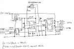
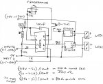
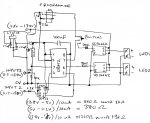
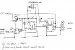
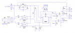
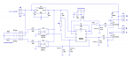
i have attached the circuit diagram and needed some help to make sure the circuit was right before building it.

circuit will be powered from a regulated 13.8v power supply and i was wondering do i need to use a regulater to power
the PIC or will a simple resistor to lower the voltage do or a some type of voltage dividers.

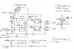
also was wondering what is the best way to calibrate the LDR to activate when it is going dark.

also will i need any pull down resistors on the input as the signal wire will be long, about 8meters.

Thanks for the help in advanced.
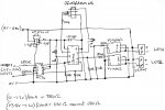
 

Attachments

techElder

Well-known member
What are the LEDs you intend to use? Those solid state relays are only rated to 50mA, and most LEDs run around 20mA for full brightness.

You could drive them easily with a 2N7000 and save some money.

I generally configure an LDR on a digital input depending on the high/low threshold voltage to do the switching from light to dark. Then I can point the LDR or shade it to pick the light it is seeing to set the visible threshold. ADC can get messy and needs adjusting anyway, so I don't want to end up outside diddling with an adjustment pot.

LDR / resistor voltage divider can be calculated to match the threshold voltage and depends on several factors; mostly the LDR.
 

AllyCat

Senior Member
Hi,

Yes, don't build that, it needs quite a lot to be fixed.

A 5 volt zener across the PICaxe rails might be one way, but that 100 ohm resistor would dissipate half a watt ! The problem with a normal 5 volt series regulator is that Input 1 and Input 2 will "Phantom power" the PICaxe (via its input protection diodes) and probably destroy the chip that way. Note that an 08M2 drains less than 1 mA for its internal circuits.

Also the vital ground connection to the Programming socket is not shown, so the PICaxe would never exit Programming mode.

Cheers, Alan.
 

techElder

Well-known member
also will i need any pull down resistors on the input as the signal wire will be long, about 8meters.
Never leave an input "floating". Always tie an input "up" or "down". Don't let its value be "unknown."

You said "pulldown" so I'm assuming these will be "active high" inputs.

It is good that you put 1K resistors in the lines. Are these lines going to switches or other digital components? You need to consider whether your PICAXE inputs can withstand "static electricity" charges. The 1K might not be enough to keep from frying your processor.

At 8 meters you need to consider the environment where the wires will be. Will there need to be filtering for AC or RF? Long lines can be antennas, too!

EDIT: PCCODER, I'd put opto-isolators on those inputs. Will solve most of the problems that you will encounter.

DATASHEET: MCT6, MCT61, MCT62 FAIRCHILD (PDF)

MOUSER: http://www.mouser.com/ProductDetail/Fairchild-Semiconductor/MCT6/?qs=sGAEpiMZZMteimceiIVCB4Jy96LwY5d2Y49m8MiFvgg=
 
Last edited:

PCCODER

New Member
input 1 is suppiled by a PIR to detect if some one is moving outside.
input 2 is suppiled by the alarm panel to say on the light when the alarm goes off.

VO14642 is a 2A soild state relay

yes they are active high inputs and yes there any be need for some AC or RF filtering.
will redo the circuit and post again with the updates.
Looks like the circuit was to simple for long turn operation.
 

PCCODER

New Member
i have added the updated circuit diagram.
have added a regulator, opto-isolator and missing ground on programming socket.

Let me know if i am still missing bits or need to any others to make it work correctly.
also i naver used a LDR before or with a PICAXE chips. so what is the best way to tune it for correct opration as
the values for the LDR i got them from the PICAXE website as they sell a small board with it on.
 

Attachments

hippy

Technical Support
Staff member
According to my notes you have the jack wired incorrectly, should be -

Sleeve - PICAXE Download Serial Out to PC RX In
Ring - PICAXE Download Serial In from Pc TX
Tip - 0V

On the upper VO14642 you might want a pull-down on the switched input, perhaps also on the other.

The MTC6 opto looks to be wired wrongly to me, and probably needs pull-ups rather than direct +5V connection. Note that top and bottom halves are mirror image circuits in the datasheet I glanced at - Okay just spotted the pin numbering !
 
Last edited:

AllyCat

Senior Member
Hi,

That looks a lot better, although some of the detail is rather difficult to follow.

You might need pullup resistors on the Opto-coupler outputs. There are "weak pullup" resistors which can be enabled inside the PICaxe by program control, but you may be more comfortable with "real hardware".

LDRs are basically quite easy to use because they do what they say - their resistance reduces with (increasing) light levels (from peraps 1 Mohm down to a few hundred ohms). So you can use an Analogue-Digital Converter input and the software can select when the light level seems low enough. This is an example where PICaxe's SERTXD command and the PE terminal emulator can come in very useful.

One issue can be that daylight levels change over an enormous range. I'm currently using a PICaxe circuit which is measuring a range of over 100,000 to 1, i.e. from bright sun down to dusk. You may find that the LDR detects "darkness" at rather higher light levels than you might expect.

Cheers, Alan.
 

PCCODER

New Member
i have updated the circuit and should be easy to ready now.

on the pull down on the VO14642 input do you mean before the 380r or after and what value do you recommand?
also the pullup on the output of the MTC6 what value so you recommand?

Thanks
 

Attachments

techElder

Well-known member
Swap the LDR and the "10K" resistor around. That way you have a "positive going" signal for the time you are trying to find --- darkness. Makes the logic easier when you can say, "If DARKNESS is TRUE ..." then turn on the lights!

Like I said before, I'd experiment a little with your own LDR to find out its resistance value at the light level you want to use. Try to match that value in a voltage divider, the "10K" resistor, so your input pin will just change logic states. That's the most stable way I've found on something like this.

If you are measuring light, then the ADC route makes some sense, but you aren't. You just want to find a level of light for detection.
 

Goeytex

Senior Member
Here's how I might do it ...

I would not use the solid state relays. The performance might be disappointing. A Logic Level power MOSFET can better handle high power LED's. The diagram shows an NTD4969N Logic Level MOSFET. With an on resistance of 19 milliohms a, heat sink will not be needed with an LED current of 2 amps. These FETs are about 50 Cents each (US).

If you still chose to use these little solid state relays, I suggest you turn the LEDS on for at least 10 min then place your finger on top of one of these chips. If you finger gets burned, then you will likely need a heat sink. Please let us know how they work out.

I show a pair of PC817D OPTOS, but any suitable opto will work. Keep the LED current at about 20 ma for noise immunity ( R12, R13). Pull down resistors R6 and R7 are needed to keep the input pins low when the external remote switches are open.

C4 is a bulk capacitor and should be located as close to the LED connectors as possible. This capacitor prevents possible voltage droop at the power supply when the LED's energize.

R10 and R11 assure that the MOSFETS remain OFF when the circuit first powers up. Any value from 10K to 100K should work OK. I show 47K.

Good Luck
 

Attachments

Last edited:

AllyCat

Senior Member
Hi PCCODER,

It does look to me as if your connections to the MTC6 optocoupler are (doubly) wrong. Firstly, the package appears to be symmetrical about its horizontal axis, so typically pins 2 and 3 would go to ground. Secondly, you appear to have wired the outputs (also incorrectly) to the supply rail, so it would need pull down resistors, which are not shown (and not available within the PICaxe).

Personally, I would not swap the LDR and pulldown resistor. Since the PICaxe inputs are "TTL compatible" their threshold voltage (typically around 1.5 volts) is nearer to ground than to the supply rail. For a low light level detector, you are more likely to want to drop a higher voltage across the LDR than the series resistor.

But I would use an ADC input. That allows you to set a threshold (purely by software control) as low as 5 mV with a normal ADC setting, or as low as 2 or 1 mV (relative to ground only) using the internal "Fixed Voltage Reference" for the ADC. You can also include some "hysteresis" in the program to avoid "dither".

Cheers, Alan.
 
Last edited:

techElder

Well-known member
Goeytex, is that the correct number for ...

The diagram show an NTD4996N Logic Level MOSFET.
Doesn't turn up on any search that I usually make.

EDIT: Sorry, I see that it is a typo in your text different than the drawing.
 

Circuit

Senior Member
The diagram shows an NTD4969N Logic Level MOSFET.
Good Luck
This is not a MOSFET that I had come across before but the datasheet from ONSemi looks interesting; a quick search of the usual suppliers (RS, Farnell, Rapid Electronics, Mouser etc.) do not show stock availability in the UK. Alternatives, Tex?
 

Circuit

Senior Member
My Mouser.com shows 6,000 + in stock.

MOUSER

UK Mouser.com shows the same.

UK MOUSER
Interesting; yes, your link does show the product; when I tried earlier I could not get a single item quote, only bulk for thousands. And when I addressed Tex, I meant Goeytex; but thanks for stepping in. I might have been misreading it, I have never dealt with Mouser. I tried a quote for ten and it comes up with very reasonable £2.37 but then wants £12-00 for shipping! I gather that UK.Mouser is simply an office so that the products can be quoted in sterling etc. but that the product is shipped from the USA. So given the lack of visible availability from the main UK suppliers I would repeat the request for an alternative...
 

Hemi345

Senior Member
Here's how I might do it ...

I would not use the solid state relays. The performance might be disappointing. A Logic Level power MOSFET can better handle high power LED's. The diagram shows an NTD4969N Logic Level MOSFET. With an on resistance of 19 milliohms a, heat sink will not be needed with an LED current of 2 amps. These FETs are about 50 Cents each (US).

If you still chose to use these little solid state relays, I suggest you turn the LEDS on for at least 10 min then place your finger on top of one of these chips. If you finger gets burned, then you will likely need a heat sink. Please let us know how they work out.

I show a pair of PC817D OPTOS, but any suitable opto will work. Keep the LED current at about 20 ma for noise immunity ( R12, R13). Pull down resistors R6 and R7 are needed to keep the input pins low when the external remote switches are open.

C4 is a bulk capacitor and should be located as close to the LED connectors as possible. This capacitor prevents possible voltage droop at the power supply when the LED's energize.

R10 and R11 assure that the MOSFETS remain OFF when the circuit first powers up. Any value from 10K to 100K should work OK. I show 47K.

Good Luck
Goey, I believe R3 is connected to the wrong side of R2.
 

Goeytex

Senior Member
Diagram Corrected ...R3/R2

The way I source parts like this, is to do a parametric search of distributors in my area. I mostly use Mouser because it is in Texas and I can get next day delivery for the price of UPS Ground Service if the order is in before 8 Pm. In the UK you have Farnell, RS and others.

When sourcing Logic Level FETs, the first metric I check is "In Stock". This weeds out stuff I can't get.

Then I check the following.

N-Channel
Through Hole
RDSON < 50 mOhms
Gate Threshold 2.8V Max

This usually leaves about 10 - 50 items that I can sort through.

So, to find a suitable replacement in UK do a parametric search of Farnell, RS, and whoever else is there. BE careful with Logic Level FETS. The Gate Threshold voltage should be 3V at the absolute max and 1.5 to 2.5 is even better.

I found this one at Farnell UK .... IPP096N03L G . There are quite a few more, so do the search.
 

Attachments

PCCODER

New Member
sorry about the delay in the replys.
i have read all the posts and i have updated the design with your suggestions and corrected a few errors.

some of the parts selection is that i have them to hand or easy to get.
have on hand 08M2, ssr VO14642, LT1521-5, leds 12v 500-750ma each.
cheap to get MCT6 from farnell.
 

Attachments

hippy

Technical Support
Staff member
@ PCCODER : That seems to be a retrograde step from what you had before. Using a simple resistor dropper from the 13.8V to supply the PICAXE would definitely not be recommended.
 

Goeytex

Senior Member
@PCCODER

Possibly you posted the wrong diagram?

As hippy noted, this last diagram has lost the regulator as well as the Opto Coupler .

And... if you apply 13.8 Volts to Pin 4 (C.3) even though a 1K resistor, the Picaxe is very likely to get damaged as there are no internal clamping diodes on this particular pin.
 

The bear

Senior Member
@ hippy & Goeytex,
I don't think this one is a five star contender!
Tex has gone very quiet.
Regards, Bear..
 

techElder

Well-known member
I can't find a way to harass you more Bear, since you are having so many problems with keeping your paper-napkin schematics organized! <BIG GRIN>

You really need to get started with the free version of DIPTRACE SCHEMATIC CAPTURE and general printed circuit software. It really makes keeping those paper things from getting the best of you!

Highly Recommended! (Hint, hint.) :)
 

Goeytex

Senior Member
I can't find a way to harass you more Bear, since you are having so many problems with keeping your paper-napkin schematics organized!
Too funny ....

I was recently forced to clean up my Lab and opened up an old file cabinet hidden away in the closet. There was a manilla folder in there containing about 50 or so old schematics that my brother and I had collaborated on dating back to 1967 when I was a freshman in High School. A couple were actually on old discolored napkins! But most were done in pencil on surplus graph paper that my dad got from from the University. I looked but could not find my slide rule.
 

The bear

Senior Member
@Tex,
Thanks for the hint, hint. I will try to mend my ways.
I was wrong, it is five star material.

Regards, Bear..
 

techElder

Well-known member
So sorry, I see that in my haste to chastise someone, I tended to chastise all engineering and technical types for seemingly common behaviour! <BIG GRIN> (Especially ME!)
 

PCCODER

New Member
sorry about that and that was my first attempt and i thought i deleted that and must have saved it in error. correct circuit now added.
the only reason i dont use schematics capture software is that they did not have the componets that i needed and doing it by hand was more easy.
lesson learnt and they do make editing more easy. i do use the diptrace PCB software already.
 

Attachments

PCCODER

New Member
Just having a little fun at your expense, PCCODER! :)
Thats ok as i made some simple mistakes that i normaily dont do.
must be the long hours... there no problem in having abit of fun, i probably would have done the same.
also i really do appreciate all the help.
 

Goeytex

Senior Member
The solid state relays will not switch properly as wired in the diagram.

The internal FETs are N-Channel and should be wired as a low side switch. Look at the datasheet page 4.

Pin 5 should be tied directly to ground. Pins 6 and 4 are tied together and go to the Cathode of the LED. The +13.5V supply goes to the Anode of the LED. Like in my diagram below.
 

Attachments

PCCODER

New Member
what schematics capture software do you recommend and i tried diptrace and cant find componemts in the standard librays that i need.
i have added a fifth revision of the circuit and i thing it many be ready now.
 

Attachments

Goeytex

Senior Member
I used MS Paint for that last one. I copied and pasted the SSR images from the data sheet and drew the lines and rectangles with the various tools. For just drawing schematics I typically use LTSpice.

If you are looking to eventually generate Gerbers for PCB production, Diptrace seems the most popular here. Eagle is another, and probably the most popular worldwide.

There will always be some components that are missing in Schematic Capture software. You can either use a generic or similar component with the same footprint or you can create your own component with the built in component editor.
 

techElder

Well-known member
And there's always Lucid Charts for an online drawing solution. It basically does flowchart type stuff, but I've drawn simple schematics with it also. Its a little more structured than MS Paint.
 

PCCODER

New Member
Hope you dont mind Goeytex as i used your drawing to make my proper schematic :).
let me know if it needs any more changing or if its ok to make the circuit.
 

Attachments

Goeytex

Senior Member
Hope you dont mind Goeytex as i used your drawing to make my proper schematic :).
let me know if it needs any more changing or if its ok to make the circuit.
Don't mind a bit. Anything I post here should be considered in the public domain and free for anyone to use, modify or whatever.

However I strongly agree with eclectic. You should absolutely breadboard and test the circuit for proper operation before committing to ordering or making a circuit board.
 
Top