How to deliver variable AC 5 - 18 volts ???

joe paul

Senior Member
Hi Folks,

It is rather simple to do PWM for DC, but is there a circuit and similarly easy way to deliver variable AC?
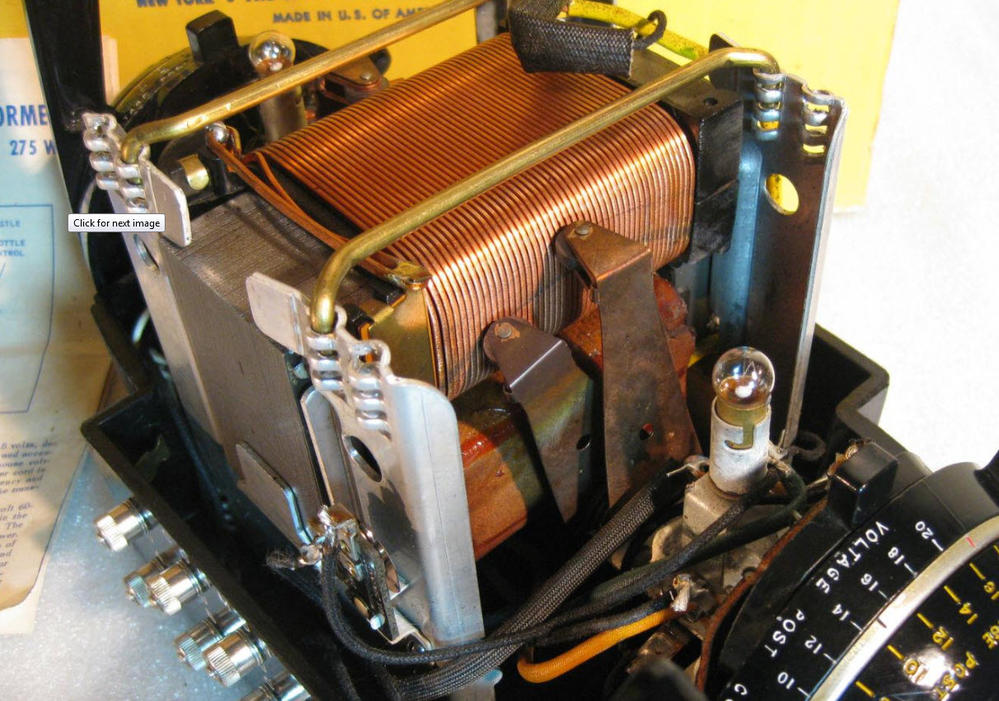
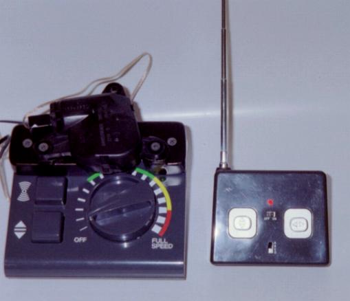
For example, I would like vary the AC from approximately 5 to 18 volts (for AC toy train control) with the 18M2 chip.

Thanks!

Take care, Joe

P.S -- I don't have an oscilloscope, so I wouldn't be able to troubleshoot the circuit. J.
 

techElder

Well-known member
With AC you would have to do some kind of phase control. That is known as a lamp dimmer elsewhere.

Timing is critical with phase control, but it has been done here.

Try a search on the forum.
 

joe paul

Senior Member
Hi Tex,

So it has been done, but I gather it isn't easy or simple. I like a challenge, but is it worth my time and within my ability as a non-electrical engineer without certain instruments?

Thanks!!!!!!!!!!

Take care, Joe.
 

Circuit

Senior Member
Initial thoughts on the subject - the normal way of PWM controlling a motor is by PWModding the maximum drive voltage through a MOSFET. Therefore, how about using http://ixdev.ixys.com/DataSheet/DS100033A(FMP26-02P).pdf which is specified for AC motor control. Given the Vgs(threshold) is a little high for logic drives you would need a MOSFET driver, but there is plenty about MOSFET drivers in this forum (some good advice from @Goeytex, I seem to remember). I think that this would allow you to PWM your AC feed just in the same way as DC is controlled. Obviously, as Tex pointed out, there are phase issues, but if you are looking at a 50/60 Hz AC waveform and, say, a 1KHz PWM then I can't imagine this being an issue. These are just some initial ideas to kick off with.
 

joe paul

Senior Member
Hi Circuit,

Thanks for the info! This is way over my head and beyond my ability. Although I am tying up extra pins on the 18M2 chip, I think is easier for me to keep doing what I already worked out, and that is to just apply fixed AC by use of several relays, one for each different preset AC voltage. I was hoping for a smoother and more elegant way of doing it, but I am really out of my league with that component and the code that would handle it. The PWM with a common MOSFET was easy with the Picaxe wizard and a little trial and error, but this seems like weeks of tinkering for me and I don't even understand it.

Take care, Joe
 

joe paul

Senior Member
Hi again, Circuit,

On second thought, if it is as easy as connecting pins 1 and 5 to the same Picaxe PWM pin, then I'll try to tackle it.


Thanks!!!!

Take care, Joe

P.S. -- It is a $16 component, would hate to ruin it. J.
 
Last edited:

Goeytex

Senior Member
With no oscilloscope and limited electronics experience it may be a challenge for you, even with the IXIS Device.

While certainly not an elegant solution, and one that others may scoff at, you could connect a servo to the knob/shaft of a variable transformer. Then with the servo/servopos commands, have the servo rotate the control shaft therefore changing the AC voltage.

It's a cave man solution that should work well.
 

joe paul

Senior Member
Hi Goettex,

Thanks for the reply and good advice.

I already do what you suggested with a cheap RC car's board, low RPM gearhead DC motor, and wireless remote:


I will convert it to Picaxe & Bluetooth when the cheap RC board fails.

Take care, Joe.
 
Last edited:

Circuit

Senior Member
Hi again, Circuit,

if it is as easy as connecting pins 1 and 5 to the same Picaxe PWM pin, then...
No, as I said, it will need a MOSFET driver to work properly - I don't believe the IXYS device is a logic-level drive MOSFET. With a Vgs(th) of 2.5 v min and 5v max it would not switch with a PICAXE chip. The PICAXE chip would be connected to the MOSFET driver and then the MOSFET driver would switch the IXYS device. You need 10 volts to switch the IXYS device properly.

I would not scoff at Goeytex's "caveman" solution - it looks quite sensible as a really simple way of achieving your aim. Clearly it would work very well; an excellent example of lateral thinking and you are remaining safely within your level of expertise.
 

joe paul

Senior Member
Hi Circuit,

Thanks for the info! I didn't scoff at Goeytex's suggestion; I've already done it (years ago) with a motor instead of a servo. (please see my photos and link on the previous page)

Take care, Joe.
 
Last edited:

tmfkam

Senior Member
Something like this will generate an AC signal between the two AC_LV terminals when fed with a suitable PWM signal from a PicAxe. The frequency of the PWM signal could be set to suit your requirements and it should deliver around 20V Pk-Pk (with a 12V supply) at something like 500mA [untested]. The PWM would need to be kept close to 50% to avoid putting DC through the load.

No parts are critical, so long as the output transistors are NPN/PNP pairs.

AC_Bridge.png

Not a perfect circuit, but I've used it many times and it has proved to be reliable and rugged.


If you need the AC supply to be isolated from the DC supply, you'd need a separate [isolated] supply for the 5V and 12V sides, with the PWM fed from the PicAxe to the AC bridge section through an Opto-Coupler or possibly a pulse transformer.
 

techElder

Well-known member
How can you generate "20V Pk-Pk" from a 12VDC supply with that circuit? There are no capacitors or inductors shown.

You makin' one of them perpetual motion machines? :)
 

tmfkam

Senior Member
By applying a variable duty PWM to the PicAxe_PWM_Power terminal, the output voltage delivery could be varied at will.

AC_Bridge_2.png
 
Last edited:

tmfkam

Senior Member
How can you generate "20V Pk-Pk" from a 12VDC supply with that circuit? There are no capacitors or inductors shown.

You makin' one of them perpetual motion machines? :)
I wish!

No, the output forms a bridge. In the first half of the cycle assume Q4 and Q7 are on. The terminal LV_AC will be close to 11V (via Q4) and the terminal LV_AC_ will be close to 0V (via Q7). On the second half of the cycle, Q5 and Q6 are on. Now LV_AC is close to 0V and LV_AC_ will be close to 11V. This gives a change in potential between the two terminals of 22V [ish] across the AC cycle .
 

Circuit

Senior Member
I wish!

No, the output forms a bridge. In the first half of the cycle assume Q4 and Q7 are on. The terminal LV_AC will be close to 11V (via Q4) and the terminal LV_AC_ will be close to 0V (via Q7). On the second half of the cycle, Q5 and Q6 are on. Now LV_AC is close to 0V and LV_AC_ will be close to 11V. This gives a change in potential between the two terminals of 22V [ish] across the AC cycle .
This would assume a duty cycle of 50%. If the PWM duty cycle is varied to control the output (which is the usual way) then an asymmetric waveform would be produced; and a square wave at that. Clearly the rate could be varied, but I doubt that varying the base frequency is quite the best way of controlling an old-fashioned AC model train motor. I would guess that the motor would be optimised to work at 50/60 Hz.

The ideal is to produce a variable voltage 50/60Hz sine wave and the simplest way to do this is probably with a variable voltage transformer. I have an old model train controller that does just that; the secondary windings on the transformer are exposed to the surface periodically during the winding process. The lacquer is abraded off the surface windings and a carbon brush is driven longitudinally across the exposed secondaries so that a true variable AC voltage is generated. I think that it is probably quite involved to reproduce this electronically - hence Goeytex's proposal. Just a note of caution; some old controllers of this type were auto-transformers and therefore did not have the safety isolation of secondary windings. I would be rather uncomfortable about using one of these today. I presume that the controllers that Joe is using at present are AC transformers that are fed through a rheostat, so the controller is actually controlling current rather than voltage. Joe, how do your existing controllers work; variable voltage transformers or rheostats?
 

joe paul

Senior Member
Joe, how do your existing controllers work; variable voltage transformers or rheostats?
Hi Circuit,

The old transformers from about 1950 have a wiper that rolls over the secondary windings (photo of the classic Lionel ZW guts):


and produces a pure sine wave. The one I used for my motorized knob contraption is fed 18 VAC from a large wall type transformer and the throttle has transistors and triacs inside the throttle housing, and I believe it produces a chopped sine wave.

Interestingly, the old motors were "universal" types that run on AC and DC, and the Picaxe's PWM (don't know about possible overheating, with the PWM). However, older and newer circuitry uses a DC offset to trigger sounds, like whistle and bell. For backward compatibility, it needs to be AC on the track with the occasional DC offset. New wrinkle -- on-board Bluetooth control will be commercially available soon (controlled from smartphone/tablet). I did my own Bluetooth/Picaxe controllers -- love them. One is on-board (in the train, a few electrical noise issues, but ok), and 2 trackside, one PWM and the other preset fixed AC voltage delivered by 5 relays (I use diode strings, diodes in pairs facing opposite directions for passing AC),


but it is bulky and needs hefty diodes, about 24 at least. So size doesn't matter trackside, but I was looking for an elegant solution. I might try that circuit from Tmfkam since it won't be costly.

Does this make sense?

Take care, Joe.
 
Last edited:

techElder

Well-known member
Joe, here's one more way to control that (or any transformer.) Its old-school industrial, but I have done the same on small scale transformers. This method does work.

Transformer core saturation.

A transformer only transfers power from its primary windings to its secondary windings because of the magnetic fields in the core (the steel.) There has to be enough steel in the core for this magnetic coupling to happen.

Assuming you have a transformer (as in the photo) that works, if you control the magnetic saturation of the core you can control the transfer of power from primary to secondary.

How to control the core saturation? With a separate winding that carries low voltage controllable DC current.

Getting the picture, yet?

Put another winding in there, create a DC current through it sufficient to saturate the core and you've got an isolated AC voltage controller.

I've actually done it with strong magnets on small transformers, too.
 

joe paul

Senior Member
Hi Texaschopper,

Thanks for the info! Wow, so much to consider!!!! I just need a 36 hour day!

Take care, Joe.
 

tmfkam

Senior Member
This would assume a duty cycle of 50%. If the PWM duty cycle is varied to control the output (which is the usual way) then an asymmetric waveform would be produced; and a square wave at that. Clearly the rate could be varied, but I doubt that varying the base frequency is quite the best way of controlling an old-fashioned AC model train motor.
My second circuit showed a way of using a second PWM input to vary the amount of DC in the output stage. If a sinusiodal output is required however, things get more complex. For the output stage to be efficient, the 'output' PWM would need to be close to 50%.
 

tmfkam

Senior Member
I would really like you to put that on an oscope and post the screen shot.
It will work. I've built small ones as this, and big ones that convert AC mains at 50Hz to AC mains with a variable frequency of 25 - 250Hz with PWM control of power delivery.

Maybe my explanation wasn't that great, but consider both the direction of current and the voltage together. If you put a voltmeter on the terminals, with Q4-Q7 on the voltmeter might indicate +11V. Leaving the voltmeter on the same terminals, with Q5-Q6 on, the voltmeter will indicate -11V. The difference between -11V and +11V being 22V. This is what the load sees, a swing in voltage (and direction of current) of 22V.

If I've still not convinced you, Google BTL circuits (Bridge Tied Load) perhaps there is a better explanation of the principle?
 

techElder

Well-known member
I'm not questioning that the voltage on one output pin with reference to the other output pin reverses polarity. I'm questioning your explanation on how that equals 22V.

One terminal goes from 0 to 11 while the other goes from 11 to 0. Inversely and opposite. Where's the adder?

To get 22V on the output, one output would have to be at 11V while the other output is at -11V. Right?

That doesn't happen. There is inversion between the output pairs. One goes up while the other goes down.

You have a reversing polarity circuit, but not a boosting reversing polarity circuit.
 

PieM

Senior Member
I agree with Tex: BTL circuit is a floating output circuit for loudspeakers. It's not an AC converter for motors.
 

techElder

Well-known member
It isn't a poll. I'm only trying to get correct information so someone doesn't go to a lot of trouble for nothing.

Getting AC by using switched DC can be important to an application. This method has been used in the drilling and seismic industries for many decades and is a good way to abate electrolysis problems in buried probes.

But you can't just manufacture voltage without some sort of storage medium for the "off" cycle.

There is no free lunch. :)
 

joe paul

Senior Member
Hi Folks,

Gee, I wish I had the experience and background (and an oscilloscope) to attempt this project with transistors/triacs, but my crude relay and diode string method isn't that bad, just ties up more pins on the 18M2. So in the future I'll go to a chip with more pins or have one chip communicate with another since I feel comfortable with the 18M2. And the DC offset is easy to do with diode strings, too, (6 one way, 1 the other).

Wave form has a lot to do with the way certain motors behave, which is a little confusing when you thought there were only 2 forms of electricity, AC or DC. Some puzzling behavior results when different "wall warts" are used. One thing I like to do is use a large electrolytic cap on most of my DC supplies, and if in a locomotive across the motor, it provides an electronic flywheel effect. There you have it -- everything Joe knows about electricity! :D

As always, thanks, everyone, for investing yourselves in my questions!

Take care, Joe
 

tmfkam

Senior Member
I'm not questioning that the voltage on one output pin with reference to the other output pin reverses polarity. I'm questioning your explanation on how that equals 22V.

One terminal goes from 0 to 11 while the other goes from 11 to 0. Inversely and opposite. Where's the adder?

To get 22V on the output, one output would have to be at 11V while the other output is at -11V. Right?

That doesn't happen. There is inversion between the output pairs. One goes up while the other goes down.

You have a reversing polarity circuit, but not a boosting reversing polarity circuit.
I'm still not convinced that I've explained this in a way that clarifies the circuit operation. I still believe I'm right. The 'load' is floating, it is suspended between the two (identical) push pull output pairs. You (PieM) mention BTL as being for loudspekers, which is indeed a common use of the circuit, but why can you not substitute a motor for a loudspeaker? Both are magnetic motive devices, one pushes a paper cone, the other a rotor arm.

Still. To prove to myself that I didn't dream the last five years of building and teaching motor principles and motor drives using devices much like the one I described, I did as was asked and built one to the design and photographed the oscilloscope.

AC_Bridge_5V.png

You'll see from this circuit that I only had BC547 and BC557 NPN/PNP transistors, and as I have no small AC motors my load is a 100R resistor. I also ran both PicAxe and output stage from the same 5V supply.

IMG20150728222433.jpg

The breadboarded circuit.
 

tmfkam

Senior Member
meter.jpg

Meter showing 5V supply.

scope.jpg

Oscilloscope showing a 250Hz square wave, and set for 2V/Div which by my calculations looks close to 8V Pk-Pk, much as I originally predicted due to losing 0.7V per active device.
 

tmfkam

Senior Member
Scope2.jpg

Finally, the oscilloscope with the information on, claiming a Pk-Pk voltage of 8.13V, from a 5V supply.
 

tmfkam

Senior Member
To get 22V on the output, one output would have to be at 11V while the other output is at -11V. Right?
This where the misunderstanding is. You're expecting both positive and negative peak voltages to occur simultaneously. In an AC waveform (single phase) derived from a transformer at no point in time do the positive and negative parts of the cycle exist in direct opposition to one another. The peak voltages are separate. First the positive half cycle reaches it's peak, this passes through zero, then the negative half cycle reaches it's peak before returning to zero at which point the positive cycle starts again. The Pk-Pk voltage is measured across the entire AC cycle, positive and negative.
 
Last edited:

Goeytex

Senior Member
If a square wave "AC" is acceptable then to have a variable voltage AC source then the DC source needs to be variable. This can be accomplished in several ways. One would be to use a digital pot such an AD5290 to act as the adjust resistor on an LM317 based power supply. The AD5290 is one of the few digital pots that can operate at the required voltages.

Using a couple of power transistor in conjunction with an LM317, the current can be quite high. eg 10 amps with an 2N3055. The Picaxe uses SPI commands to adjust the DC voltage. The output then goes to to an H-Bridge type circuit where the AC is produced. I used a Picaxe and an H-Bridge to produce a 24VAC square wave for use in a Colloidal Silver Generator and it works quite well.

Another option is to use a digital pot (SPI/I2C) to control the FB pin on a switcher IC to adjust the output voltage of an SMPS. Possibly one of those cheap EBAY switchers could be hacked if it can supply adequate current.

The bottom line is having a programmable power supply of some kind to adjust the DC voltage to the Bridge Circuit .

If a sine wave is required, all bets are off.

Attached is an example diagram of a high current Programmable Power Supply using an LM317. (Untested)

Edit: The diagram shows a 28V DC supply source. However a 24V supply should work fine and verifies to work in SPICE.
I have built and verified this circuit using a standard Pot, but it has not be verified with the AD5290.


Note: SPICE is a wonderful tool for circuit design and can save the designer a lot of time in the design process. But it should never be used as a substitute for actually building and testing a circuit.
 

Attachments

Last edited:

tmfkam

Senior Member
It should be possible to provide a variable AC supply using a circuit similar to this:

AC_Rectifier_Power.png

Just in case I'm accused of waking up with my head in the cornflakes again, this circuit is a derivation of this design from ST.

ST_Design.jpg

The full description of the circuit operation can be found here: http://large.stanford.edu/courses/2012/ph240/johnson2/docs/CD00003922.pdf

To save you reading too much, as the low voltage supplies are taken across the active device, which needs to be on for current to flow in the motor (shorting the low voltage supply out temporarily) it is recommended that the duty of the PWM does not exceed 90% (the 10% will hopefully recharge the low voltage supply).

The output wil be 'sliced sinusoidal' with the width of the slices being determined by the PWM duty. This in turn will vary the power available to the motor. The fact that it is sliced should be smoothed to some degree by the inductance of the motor and shouldn't affect the operation of the motor significantly.

For PWM control of the AC supply, I'd be tempted to start the PWM frequency at a minimum of 10 x AC mains supply frequency (10x50Hz=500Hz minimum). I never got round to making one of these designs, it was next on my list prior to leaving but I see no reason why it shouldn't work. Now I'd be interested to see this on simulated in Spice or similar, or built in silicon would be even better...
 

tmfkam

Senior Member
Using a couple of power transistor in conjunction with an LM317, the current can be quite high. eg 10 amps with an 2N3055. The Picaxe uses SPI commands to adjust the DC voltage. The output then goes to to an H-Bridge type circuit where the AC is produced. I used a Picaxe and an H-Bridge to produce a 24VAC square wave for use in a Colloidal Silver Generator and it works quite well.
Could the switching here be done quickly enough to generate an approximate sine wave? Ramping up and down fairly quickly? This could then be passed on to a bridge output stage to provide the AC 'swing' above and below 0V in the load. Obviously you'd need zero crossing detection to ensure the output stage 'switched' at the zero (or near zero) point but if this was all done in the same PicAxe it could be done.
 
Top