hall effect switch, normally on

steviejay

Member
Hi all

I cant seem to establish which hall effect switch(not analogue sensor) is normally on. I bought some OH3144E Hall Effect switches but it turns out that they are normally off. Im building an 08m2 timer and have been using reed switches but want to try a switch. I have tried the analogue sensors but had too much trouble setting interrupts.

So can anyone tell me a part number/model for a normally on hall effect switch

thanks for taking the time

Steve
 

techElder

Well-known member
I don't know how you are determining "ON" and "OFF", but this device has an "open collector" output.

PIN 1 = VCC, PIN 2 = GND, PIN 3 = OUTPUT.

You have to connect a resistor (1K?) from PIN 3 to VCC to be able to see the output work.

Do this and when you apply a magnetic field, the output will go LOW. The output transistor conducts when a magnetic field is applied.

BTW, this device has been discontinued since 2005.
 

steviejay

Member
thanks Tex

so how do I get a hall effect switch to act in the same way as a reed switch?

Way back on the forum I tried to get an analogue hall effect sensor to operate an interrupt on the 08m2. I could debug to get levels for acting as a trigger for my timer but couldnt interrupt.

So ive made a few that work really well using reed switch, easy to interrupt, but the commercially made ones use a hall effect

http://www.trademe.co.nz/sports/fishing/salt-water/kontikis-kites/auction-911561093.htm

Im trying to use mostly the same code but changing a reed for a hall effect

thanks for taking the time

Steve
 

rq3

Senior Member
Hi all

I cant seem to establish which hall effect switch(not analogue sensor) is normally on. I bought some OH3144E Hall Effect switches but it turns out that they are normally off. Im building an 08m2 timer and have been using reed switches but want to try a switch. I have tried the analogue sensors but had too much trouble setting interrupts.

So can anyone tell me a part number/model for a normally on hall effect switch

thanks for taking the time

Steve
Steve, your mention of interrupts makes me think a picaxe is involved here somehow? Could you just use the picaxe to detect the hall effect switch, and invert the response if you need to?

Rip
 

techElder

Well-known member
I see what you are doing now, but I can't see any need for an "interrupt" for this timer application.

You have to tell us what circuit you are switching. Just saying "reed relay" doesn't describe the circuit. The relay contacts could pull a line up or pull a line down.

Circuit diagram?
 

steviejay

Member
I see what you are doing now, but I can't see any need for a"interrupt" for this timer application.

You have to tell us what circuit you are switching. Just saying "reed relay" doesn't describe the circuit. The relay contacts could pull a line up or pull a line down.

Circuit diagram?
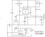
08m2 timer schematic with 3v nov 14.jpg

Thanks

tried to attach file


Im aiming to replace the reed switches with a hall effect, trying to use the same-ish code without having to set analogue parameters, for when I have a problem and I need the interrupt to reset using the magnet.

thanks again
Steve
 

techElder

Well-known member
Steviejay, apparently you are using the term "interrupt" to mean something that cuts the power to the motor. (There is a function in a PICAXE that is called an "interrupt", but means something totally different.

What problem are you trying to solve by replacing the reed switches?

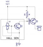
Those reed switches are wired as pull-up switches. You will have to add the hall sensor, a PNP transistor and a resistor to replace each reed switch. Is it still worth it?

EDIT: HallGenSwitch.jpg

EDIT #2: Fixed the schematic. AllyCat caught my screw up. It is too easy to put junk out! :)
 
Last edited:

AllyCat

Senior Member
Hi,

Beware that a "Hall Switch" and a Reed Relay have very different characteristics. Firstly the Hall switch is a "three terminal" device (Supply, Ground and Output) whilst a Reed switch has only two terminals. The OH3144E which you quote specifies a minimum of 4.5 volts on its supply rail. but you appear to be using a 3 volt battery?

Another difference is that the Reed Switch will respond to both (or either) a North Pole and South Pole magnetic field, but the Hall switch usually to only one polarity.

For your modification, you probably need to replace the reed, the pull down resistor and the capacitor (which suppresses contact bounce). Removing those gives you the three terminals where you might connect the Hall device. If it's an open collector type (like your OH3144E) then it will require a (10k) resistor as "pull up" (i.e. to the supply rail). Then you need to identify whether your operating magnet fields are positive or negative (North or South poles). Then you can try to identify a Hall switch with the correct type of characteristic, which may not be easy as there are many different parts of the specification to consider.

As Tex implies, why are you attempting to replace the reed switches? They're still available and can be very reliable.

Cheers, Alan.

PS: In Tex's diagram, the (PNP) emitter should go to the supply rail (Vcc), and there should be a resistor in series with its base. But whether such an inverter is required will depend on the type of Hall device (and operating magnetic field), as I've outlined above.
 

steviejay

Member
picaxe kontiki timer 3v.png

thanks for all of this help, this image is the actual thing, except Ive added a capacitor across the 3v to iron out rattle in the 3v holder(seems to have fixed it, it was resetting randomly)

so the interrupt code (setint %00001000, %00001000,c)just means of I pass the magnet across reed 2 it resets the 08m2 and turns the motor off wherever it is up to in the timer code

as for the reed switches, they seem to be tough, this thing as been going to sea for a year and is still going(though the RC snubber across the relay has rusted out and its still going ok)

but for my next version I wanted to use hall effects like they do on the bought ones, I also want to devise a front end rudder servo usng both compass and gps(like the bought ones do, http://kontiki.co.nz/

thanks for all the input, I will source a few hall effects and mess with them. I have used them as analogue so can set up debug etc...but somethin on/off is my mission. I will have to lift the voltage on the picaxe side, I tried to use the 12v and regulator but had no end of trouble with the picaxe resetting...no amount of capacitor levelling/snubbing helped..so I went for separate supply

steve
 

ZOR

Senior Member
Hope nobody goes out there swimming. Can't see this was ever allowed. Fishings one thing but this is not playing the game. Hope a shark takes the leader out!
 
Top