More inputs and outputs needed

lbenson

Senior Member
Breadboard images for slave 40x2 and MCP23017

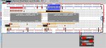
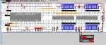
Attached are two breadboard images from westaust55's excellent pebble program. The first shows 2 40X2s in master/slave configuration, the second is one I had previously drawn up for a 40X2 and 2 MCP23017s.

Note that the breadboards are in places more suggestive than definitive. The LEDs with no resistors come with built-in resistors, Digikey 67-1103-ND. For the LEDs which are shown with resistors, the resistors are in-line with the LEDs, not plugged into the breadboard column as shown. The SIL 10K pulldowns are something you might not have in your parts box--they are for preventing false triggering of the inputs due to noise.

The master/slave setup shows as examples one input port on the slave (portB), and one output port on the master (also portB).
 

Attachments

Last edited:

koyli

Member
I have to thank you again for your patience on this subject. Putting new ideas into an old brain os not as fast as a young one.

I can understand that going from flowchart to basic could seem daunting, but I would think that a flowchart controlling over 100 I/Os would be extraordinarily complex, if even possible.
Yes, I know it will be impossible, but I have seen how the compiler converts the flowchart into code and am learning from that.
The code reminds me of my old Sinclair Spectrum+2. I used to have some code to expand the Speccy`s backport but I cannot find it now. That would be just the job.

Anyway, I will try your examples over the next few days.
 

lbenson

Senior Member
This brain is approaching its 8th decade, so I'm hoping that this electronics hobby keeps the cells stirred.

Note that you can replicate the breadboard shown above to add two more 40X2 slaves, giving you on the order of 116 I/Os. All you need do is remove the battery (or other) power supply and the two 4.7K resistors on the I2C lines on the second board, and connect the two boards with 4 wires--5V, 0V, I2C SDA, and I2C SCL.

By the way, I had not heard of a lever frame before (not being current with model railroading). Is it something like the one shown here: http://modratec.com/

Can you post a pic?

Does this imply that to a large degree your picaxe outputs will reflect the inputs from the lever frame?
 

Dartmoor

Member
@ lbenson - yes that link is a lever frame.That has mechanical locking built in, but I believe Koyli is trying to use picaxes instead of mechanical locking?
Post #18 suggests that the outputs from the picaxe will drive lamps/LED's to say that it is OK to pull the lever which will operate the points/signal, rather than control the points/signal directly.

I have done this before by feeding all inputs (track circuits, point detection/sense, lever position etc) into a PC (could equally be a Picaxe). Then check the that points, track circuits and lever positions are in the exact combination in the PC/Picaxe before driving the corresponding outputs to operate signals and points.

The neat thing with Modratec is that you can draw your track layout with signals & points and their software converts that into mechanical locking. They then send you a customised kit of parts to build it!
I will point out that I have no connection with the company & have not even bought one! (but I have seen one).
 

lbenson

Senior Member
I apologize if I am taking a greater interest in this project than the OP might desire (especially considering my ignorance of the model railroading field). I am attaching a program which has the structure for processing 43 inputs from 2 slave 40X2 picaxes.

It resolves down to testing whether bit0 is 1 or 0 for each of 48 possible inputs (of which 5 are excluded because they represent the C.3 and C.4 i2c ports and the A.4 serout port on the slaves). The program compiles in PE6, but is otherwise untested.
Code:
' 40ModelRailroad reads 43 inputs, controls 73 outputs using 3 slave 40X2 picaxes
#picaxe 40x2
symbol bitCounter  = b37
symbol loopCounter = b38
symbol portCounter = b39
symbol masterPortB = b40
symbol masterPortC = b41
symbol masterPortA = b42
symbol masterPortD = b43
symbol slave1PortB = b44 ' input 8 bits
symbol slave1PortC = b45 ' input 6 bits
symbol slave1PortA = b46 ' input 7 bits
symbol slave1PortD = b47 ' input 8 bits
symbol slave2PortB = b48 ' input 8 bits
symbol slave2PortC = b49 ' input 6 bits
symbol slave2PortA = b50
symbol slave2PortD = b51
symbol slave3PortB = b52
symbol slave3PortC = b53
symbol slave3PortA = b54
symbol slave3PortD = b55

  hi2csetup i2cmaster,%10100000, I2Cslow, i2cbyte
  pause 40
do
  hi2cin [%10100000],0,(slave1PortB,slave1PortC,slave1PortA,slave1PortD)
  hi2cin [%10100010],0,(slave2PortB,slave2PortC)
  ' now do what you need to do with the 46 bit values
  bptr = 40
  portCounter = 0
  for loopCounter = 1 to 6 ' for each byte of input bits
    b0 = @bptrinc ' move through the 6 bytes of inputs
    for bitCounter = 1 to 8
      inc portCounter
      select portCounter
        case 1   ' add code for what you do with input 1
            if bit0 = 1 then '
            else
            endif
        case 2 
        case 3 
        case 4 
        case 5 
        case 6 
        case 7 
        case 8 
        case 9 
        case 10 
        case 11 ' null--i2c slc
        case 12 ' null--i2c sda
        case 13 
        case 14 
        case 15 
        case 16 
        case 17 
        case 18 
        case 19 
        case 20 ' null--portA.4 output only
        case 21 
        case 22 
        case 23 
        case 24 
        case 25 
        case 26 
        case 27 
        case 28 
        case 29 
        case 30 
        case 31 
        case 32 
        case 33 
        case 34 
        case 35 
        case 36 
        case 37 
        case 38 
        case 39 
        case 40 
        case 41 
        case 42 
        case 43 ' null--i2c slc 
        case 44 ' null--i2c sda 
        case 45 
        case 46 
        case 47 
        case 48 
      endselect
      b0 = b0 >> 1 ' shift right--bit 1 becomes bit 0
    next bitCounter
  next loopCounter
loop
Following a structure like this would leave the OP the task of determining the logic for setting the outputs based on these inputs. I realize that there's not going to be a 1-for-1 relationship between single input port states and outputs, but the inputs could be used to set additional bits in bytes 1-3 (and elsewhere as needed), and the outputs could be set based on those.

I hope that one of the things which more experienced picaxe programmers can do to help newcomers who have ambitious projects is to provide a program structure which allows them to work on what they really want to do--develop the logic to handle their inputs and outputs.
 
Last edited:

edmunds

Senior Member
I hope that one of the things which more experienced picaxe programmers can do to help newcomers who have ambitious projects is to provide a program structure which allows them to work on what they really want to do--develop the logic to handle their inputs and outputs.
Excellent post. Thank you for your input on the forum. I agree (from my own experience) this is a very efficient way to learn and keep learning, because with this sort of help there is a pretty good chance to win the challenge before feeling all too lost and giving up on it :).


Edmunds
 

koyli

Member
By the way, I had not heard of a lever frame before (not being current with model railroading). Is it something like the one shown here: http://modratec.com/

Can you post a pic?

Does this imply that to a large degree your picaxe outputs will reflect the inputs from the lever frame?
Here are two pics of what I am attempting to build.
This is Manchester Victoria West Junction
ManVicWest2.pngManVicWest.png
 

techElder

Well-known member
koyli, now I know how my wife felt when I was explaining the logic involved in my last project just to get the right color of LED to come on. ;)
 

koyli

Member
I have now got a 40x2 and a MCP23017 connected together and working with westaust55`s code. It worked first time.

I have read through everyone`s code several times and though it is helping me to understand the data sheet`s and the syntax, none of them do exactly what I need.

If I could ask for your patience one more time to get me going, then I will be out of your hair.

Right this is it.

Say I have a 40x2 with two 23017 expanders. If the ports on the 40x2 are port`s A,B,C and D and we call the port`s on the expanders E,F,G and H then this is what I want to do.

Code:
If pin.E.2=1 and pin.E.5=1 and pinG.4=1 then
           high B.3
endif

if pinF.5=1 and pinG.6=1 or pinH.2=0 then
          highC.7
endif
and so on.

Any help will be most welcome.
 

lbenson

Senior Member
Following the code in the link provided by "Circuit" in post 24
Code:
#picaxe 14M2 
SETFREQ M16

SYMBOL mcp23017 = %01000000 ; $0100 A2, A1, A0, R/W all connected to 0V
SYMBOL IODIRA = $00 ; Port A IO Direction register DEFAULT = I/P
SYMBOL IODIRB = $01 ; Port B IO Direction register DEFAULT = I/P
SYMBOL IOCON = $0A ; IO Expander config register - address $0B accesses the same register
SYMBOL GPIOA = $12 ; Port A General purpose register
SYMBOL GPIOB = $13 ; Port B General Purpose register
SYMBOL OLATA = $14 ; Port A latch register
SYMBOL OLATB = $15 ; Port B latch register

  pause 8000
  HI2CSETUP i2cmaster, mcp23017, i2cFAST_16, i2cbyte
'  HI2CSETUP i2cmaster, mcp23017, i2cSLOW_16, i2cbyte
  PAUSE 400

  HI2COUT IODIRA, ($FF) ;set all port A pins as inputs (1)
  HI2COUT IODIRB, ($FF) ;set all port B pins as inputs (1)

   PAUSE 100

    HI2CIN GPIOA,(b0) ' 
    sertxd(#b0)
    HI2CIN GPIOB,(b1) ' 
    sertxd(#b1)
Then your ports E an F are in b0 and b1. Do the same for your second MCP23017 to read inputs into b2 and b3. Then you can access the values with the bit variables, bit0-bit31:
Code:
' If pin.E.2=1 and pin.E.5=1 and pinG.4=1 then
if bit2 = 1 and bit5 = 1 and bit20 = 1 then '
To make things clearer, you could define the bits:

symbol pinE2 = bit2
symbol pinE5 = bit5
symbol pinG4 = bit20

Then: "if pinE2 = 1 and pinE5 = 1 and pinG4 = 1"

If you have values in b0-b3 which you want to preserve, then you can preceed this code with "push b0,b1,b2,b3", and follow it with "pop b3, b2, b1, b0".

But you might want to define with more meaningful names:

symbol somethingSignificant = bit2
symbol somethingElseSignificant = bit5
 

koyli

Member
Thank you, thank you, lbenson. That is exactly what I needed to know. It is all becoming much clearer now.

Just one small point. At the top of the code is
Code:
#picaxe 14M2
Is it just the same for a 40X2?
 

edmunds

Senior Member
Just one small point. At the top of the code is
Code:
#picaxe 14M2
Is it just the same for a 40X2?
It does not have to be there even. But if you want it, then it should be #picaxe40x2. It makes life a little easier since it tells the compiler what chip to compile for and you don't have to set it up in the options. #picaxe14M2 (without a space) will not be downloaded with #picaxe40x2 connected. MacAxepad asks if you want to change the setting to the right hardware and does it for you if you click OK. Don't know about PE.

Edmunds
 

westaust55

Moderator
I have now got a 40x2 and a MCP23017 connected together and working with westaust55`s code. It worked first time.
With the control bit for IOCON.BANK = 0
the registers for the two IO Expander ports are in two consecutive registers $12 and $13,

Thus instead of two separate Hi2cIN commands as:
Code:
HI2CIN GPIOA,(b0) ' 
    sertxd(#b0, " ") ; a space inserted to separate the displayed values
    HI2CIN GPIOB,(b1) ' 
    sertxd(#b1,CR,LF); CR,LF moves display to a new line for ease of reading
this can be reduced to:
Code:
HI2CIN GPIOA,(b0,b1) ' 
    sertxd(#b0, " ", #b1,CR,LF)
There also exists the option to use an interrupt signal from the MCP23017 to the PICAXE chip. This does require 1 or more input pins on the PICAXE chip.
Set up correctly for interrupt on change of state (as opposed to change from a default) this can be used to load the input register values only when a pin has changed state and flag to the main PICAXE program a need to action a change of outputs based on your interlocking logic. This would save the PICAXE having to keep reading the MCP23017 ports over and over to check for any changes in the input pin states.
Just something else for you to experiment with prior to any final decisions on how to write the final PICAXE code.
 

koyli

Member
I have given a bit of thought to this and have changed the strategy so as to use two PICAXE 40X2`s with two expanders each and use logic gates to combine the turnouts and track circuits into seperate routes, so that one pin only is needed to read each route.

However, I still cannot get the inputs down to 32 for each pair of expanders. If I add a third (or fourth) expander, how do I read the inputs while keeping the first 32?
I have had several attempts, but nothing has worked completely so far.

The nearest I have come is to use

Code:
put b0,b1,b2,b3
This give me the second set of 32, but I cannot get the first set back with

Code:
[CODE]get b0,b1,b2,b3
[/CODE]

push gives a syntax error in the VSM simulator.

If we call the expander ports E&F, G&H, J&K etc, how can I do this;-

Code:
if E,2 = 1 and F.3 = 1 and J.5 = 1 then
 

lbenson

Senior Member
>how can I do this: if E,2 = 1 and F.3 = 1 and J.5 = 1 then

This is where the non-existent command, "bitX = getbit var,bit", or "getbit var,bit,myBit" (to correspond to setbit and clearbit) would be of help. You could read ports J & K into any upper named register and retrieve any bit. The alternative is to read the MCP23017 byte into an upper register, say b4, and retrieve the desired bit like this: "myBit = b4 >> bitNumber & %00000001"
Code:
#picaxe 28X2

b4 = %10101010

bit3 = b4 >> 3 & %00000001
bit4 = b4 >> 4 & %00000001

sertxd("Bits 3 & 4: ",#bit3, " ",#bit4,cr,lf)
Of course, you can use any bits and any bitnames (symbols) you like. Remember that you can give variables multiple names--you just have to use care to be sure that you're not trying to pour two liters into a 1-liter bottle by trying to use both simultaneously:
symbol pinE2 = bit2
symbol pinI2 = bit2

If push and pop aren't implemented in the VSM simulator, then if you have ram available, you can do "poke 56,b0,b1,b2,b3" to save current values to upper ram, and "peek 56,b0,b1,b2,b3" to retrieve. You can save a second bank with "poke 60, ...".
 
Last edited:

koyli

Member
The command
IF BIT
http://www.picaxe.com/BASIC-Commands/Program-Flow-Control/if-bit/
With an X1 or X2 part Will help you with test a bit in any predefined variable (eg b4 or b5)
westaust55
Thankyou for staying with this thread. How did you get to these BASIC commands? Whenever I click on that link I get something completely different.

I have spent all today wrestling with this and getting nowhere. If I had`nt had new windows fitted, the whole shebang would have gone through it by now!

Everybody has done their best and posted code that should have solved the problem, but the list of non-running programs just gets longer.

Your code above is the simplist yet and would fit the bill perfectly, if I could get it to work.

Have a look at this code and see why the output remains on all the time, nomatter what the input is.

If I cannot get this to work in the next few days then I am going to ditch the lot!

Code:
#picaxe 40X2 
SETFREQ M16

SYMBOL mcp23017a = %01000000 ; $0100 A2, A1, A0, R/W all connected to 0V
SYMBOL mcp23017b = %01000010
SYMBOL mcp23017c = %01001110
SYMBOL IODIRA       = $00 ; Port A IO Direction register
SYMBOL IODIRB       = $01 ; Port B IO Direction register
SYMBOL IPOLA        = $02 ; Port A Input Polarity Register
SYMBOL IPOLB        = $03 ; Port B Input Polarity Register  - not used in this code example
SYMBOL GPINTENA = $04 ; Port A GPIO Interrupt on-change pins 
SYMBOL GPINTENB = $05 ; Port B GPIO Interrupt on-change pins - not used in this code example
SYMBOL DEFVALA   = $06 ; Port A Interrupt register default value
SYMBOL DEFVALB   = $07 ; Port A Interrupt register default value - not used in this code example
SYMBOL INTCONA   = $08 ; Port A Interrupt Control Register
SYMBOL INTCONB   = $09 ; Port B Interrupt Control Register - not used in this code example
SYMBOL IOCON       = $0A ; IO Expander config register  - address $0B accesses the same register
SYMBOL GPPUA      = $0C ; Port A GPIO Pull-up resistor register
SYMBOL GPPUB      = $0D ; Port B GPIO Pull-up resistor register - not used in this code example
SYMBOL INTFA        = $0E ; Port A Interrupt Flag Register
SYMBOL INTFB        = $0F ; Port B Interrupt Flag Register - not used in this code example
SYMBOL INTCAPA   = $10 ; Port A Interrupt Capture Register
SYMBOL INTACPB   =  $11 ; Port B Interrupt Capture Register - not used in this code example
SYMBOL GPIOA       = $12 ; Port A General purpose register
SYMBOL GPIOB      = $13 ; Port B General Purpose register
SYMBOL OLATA      = $14 ; Port A Output Latch register
SYMBOL OLATB      = $15 ; Port B Output Latch register

  pause 8000
  
  
  HI2CSETUP i2cmaster, mcp23017a, i2cFAST, i2cbyte
'  HI2CSETUP i2cmaster, mcp23017, i2cSLOW_16, i2cbyte
  PAUSE 400

  HI2COUT IODIRA, ($FF) ;set all port A pins as inputs (1)
  HI2COUT IODIRB, ($FF) ;set all port B pins as inputs (1)
  pause 100

HI2CSETUP i2cmaster, mcp23017b, i2cFAST, i2cbyte
 ; HI2CSETUP i2cmaster, mcp23017, i2cSLOW_16, i2cbyte
  PAUSE 400

  HI2COUT IODIRA, ($FF) ;set all port A pins as inputs (1)
  HI2COUT IODIRB, ($FF) ;set all port B pins as inputs (1)
  pause 100
  
 HI2CSETUP i2cmaster, mcp23017c, i2cFAST, i2cbyte
 ; HI2CSETUP i2cmaster, mcp23017, i2cSLOW_16, i2cbyte
  PAUSE 400

  HI2COUT IODIRA, ($FF) ;set all port A pins as inputs (1)
  HI2COUT IODIRB, ($FF) ;set all port B pins as inputs (1)
  pause 100 
  
  
main:		
    HI2CIN [mcp23017a], GPIOA,(b0) ' 
    sertxd(#b0)
    HI2CIN GPIOB,(b1) ' 
    sertxd(#b1)
   
    HI2CIN [mcp23017b], GPIOA,(b2) ' 
    sertxd(#b2)
    HI2CIN GPIOB,(b3) ' 
    sertxd(#b3)
    
    
   HI2CIN [mcp23017c], GPIOA,(b4) ' 
    sertxd(#b4)
    HI2CIN GPIOB,(b5) ' 
    sertxd(#b5) 
    
    
    if b4 bit 3 set then
	gosub flash    
else	
	low B.0  
endif
goto main    
    
flash:
for b10 = 1 to 5
high B.0
pause 500
low B.0
next 
return
 

lbenson

Senior Member
You don't make clear the entire scope of the problem you are seeing--with all the MCP23017s or just the third one?

If all your wiring is right (e.g., RESET tied high, not low, all 3 address pins tied high on MCP23017 #3 as per your address of %01001110, wiring similar to the second image I posted in post 41), then it might be as simple as your not having a "pause 500" after "low B.0" in your flash routine--the "low B.0" is followed so quickly with "high B.0" that you can't see it.

Otherwise, post a clear photo of your setup (I know, it may be messy) so that we can see if anything is obviously wrong. Are you sure you are bringing the pin A.3 on the 3rd MCP23017 high and low? Are you able successfully to read the other ports?

What do you get if, after you read MCP23017 #1, you execute "sertxd("%",#bit0,#bit1,#bit2,#bit3,#bit4,#bit5,#bit6,#bit7,cr,lf)?

I can assure you from experience that it works for 2 MCP23017s, and there's no reason it wouldn't work for 3 or more.
 

westaust55

Moderator
You are not setting the internal pull-up resistors with the GPPUA and GPPUB registers = $FF.
Therefore are you using external pull-up or pull-down resistors?

Your schematic showing how wired will be useful.
 

koyli

Member
IT`S WORKING!!!!

Perseverence pays off in the end. The culprit all along was the VSM simulator. It seems that it cannot simulate the expanders and/or the i2c connection correctly.

After my rant yesterday I decided to build the circuit and test it for real. I was using the simulator to avoid constantly downloading to the PICAXE chip.

So, to anyone reading this, do not trust the VSM simulator completely.

I cannot upload a photo of my test setup or the DSN. file. The upload manager is rejecting them.

The leaning curve is easing slightly. I was on the vertical bit, but it is now about 80%.

Now I (with all your help) have got it working, accepting inputs, I have turned to the output side.

I can output to the entire port with

Code:
[color=Blue]HI2COUT [/color][color=Black]OLATB,[/color][color=Blue]([/color][color=Navy]%00000100[/color][color=Blue])[/color]
but this will overwrite any data already there. I need a way to write to each individual pin on a certain port, just as on the PICAXE itself.

I read somewhere in the manual about masking certain pins in a port, but I cannot find it now.

Any ideas?
 

westaust55

Moderator
Read the OLAT<x>register, then modify the bit you wish to change and finally write back to the OLAT<x> register.

Alternatively keep a copy of the data sent to the output port in a PICAXE variable and modify as required and write to the output port.
 

koyli

Member
O yes! Rock on Tommy. That works brilliantly.

I can`t stop looking at the led`s flashing on and off.

I`m just about ready to start writing the code for the interlocking.

I have just one more point which I think would be better in a new thread.
 

Frank42

New Member
Koyli's point about "written by experts" is all too common and the PICAXE manuals expect more than a basic level of understanding. Errors in the use of English don't help.
I wonder if proof-readers are extinct.
 

westaust55

Moderator
Koyli's point about "written by experts" is all too common and the PICAXE manuals expect more than a basic level of understanding. Errors in the use of English don't help.
I wonder if proof-readers are extinct.
I am not doubting that there may be some typo errors. It would be far more useful if you were to clearly identify what you have found for Revolution Education / PICAXE.com to take on board.
Sometime the error has been corrected or explanation clarified / expanded upon in the on-line version of the commands.
 

Frank42

New Member
It's not the typos that bother me. I've sent them some which have been corrected in the latest issue, but there's too much expertise expected of readers. I know you can use "search" but an index would be helpful. Partly because this forum has been going so long, it is difficult to find the answer to a problem as there are so many entries. I've often given up and tried to solve the problem with assembler in a "naked" PIC.
 

Frank42

New Member
I wish it was like that, but unhelpful error messages (eg. Syntax error with no further explanation) are just an irritation.
 

techElder

Well-known member
I've never had a "Syntax error" from a PICAXE editor where I couldn't fix the problem. :)

The problem was never with the editor or PICAXE Basic; always with my code.

I've never used the VSM Simulator or anything "flowchart", and I've never had a problem changing one byte in code and testing on real hardware ... over and over and over ... :)

The whole point of code is to make hardware work as planned. Dithering around about manual typos just puts you further from that goal.
 
Top