Touch16
- Thread starter techElder
- Start date
techElder
Well-known member
I've read that, too, many times. However, there does seem to be a difference if the touch pin is an output before using TOUCH16.
In my app I get readings that are maxed out at 1023 if the pin is an output before using TOUCH16.
If I add "INPUT pin" before the TOUCH16 then I can actually use the command as expected. I didn't expect to have to do that.
I was thinking that configuring a pin for ADC disconnects the digital I/O lines internally to the PICAXE.
Thus my original question ...
Are the readings otherwise the same?In my app I get readings that are maxed out at 1023 if the pin is an output before using TOUCH16.
techElder
Well-known member
28X2 on the AXE401 Shield Base
I know that the max is 10 bits. I was experimenting with starting a reading from an output low condition.
All I get is a reading of 1023.
Then if I put an INPUT command in front of the TOUCH16 command I do get readings that I can adjust with the [config] byte.
Seems strange that TOUCH16 wouldn't configure the pin as ADC in this case.
rq3
Senior Member
Tex, I had the same frustration, but did get it to work very reliably. I found during troubleshooting that monitoring the touched and untouched readings with a laptop running on only it's own battery was a HUGE help (no ground loop through the wall wart).It is so irritating that a TOUCH program will work with the AXE027 connected, but not when disconnected.
Troubleshooting is more like black magic than an RF circuit is.
I also found that the cryptic "variables" available in the TOUCH16 command had a huge effect, although they are not well explained. Ultimately I tried to get the maximum difference between the touched and untouched conditions, without data "roll-over".
The final aha moment was to have the code repetitively calibrate itself. At start up, it assumes there is no touch, and stores the touch16 value. Any value larger than that is considered a touch.
Rip
techElder
Well-known member
rq3, your touch program is what gave me some of the ideas that I'm using in mine! Thank you very much! I'm not ready to explain the difference, but I will.
I just couldn't figure out how there could be a ground loop when there is a switching power supply, but I haven't actually checked mine to see if there is ohmic isolation between input and output.
I'm getting ready to troubleshoot it with a laptop and a terminal program, but I don't have a PC laptop, so there will be some back and forth before I get it right or ....
rq3
Senior Member
Tex, I do all of my Picaxe development and programming on a really antique Dell laptop. The "wall wart" is more of a "cord brick", and definitely has a ground connection between the USB port (for the Picaxe programming cable) and the house ground. I do know that if I run the laptop strictly on internal batteries, with the charger disconnected, the odd-ball touch stuff goes away, as reported by sertxd embedded in the code while troubleshooting.rq3, your touch program is what gave me some of the ideas that I'm using in mine! Thank you very much! I'm not ready to explain the difference, but I will.
I just couldn't figure out how there could be a ground loop when there is a switching power supply, but I haven't actually checked mine to see if there is ohmic isolation between input and output.
I'm getting ready to troubleshoot it with a laptop and a terminal program, but I don't have a PC laptop, so there will be some back and forth before I get it right or ....
I can't remember if I posted the code I was using, but would be happy to post a stripped down version. Or even the whole thing if you want (which includes stepper motor drive, I2C communication, barometer reading, OLED displays, blah, blah blah). I'll warn you up front, it's ugly. It may be good for laughs, but it does work.
Rip
rq3
Senior Member
A short, bad, video of my touch switch functions on a Picaxe 20M2:
https://www.youtube.com/watch?v=MygUduY3FNM
Rip
https://www.youtube.com/watch?v=MygUduY3FNM
Rip
Last edited:
rq3
Senior Member
Tex, my apologies. Try the new link here:Unfortunately, YouTube says the video is "private."
https://www.youtube.com/watch?v=MygUduY3FNM
If I do one YouTube a decade, that's a lot, and I try to avoid Google and their minions whenever I can.
Rip
techElder
Well-known member
Very interesting, Rip. You mentioned "double-sided" board for the switches. Did you use the copper on the other side of the board? Or was the other side left alone and perhaps connected to ground?
I was interested in creating my touch pad with all of the app's electronics on the other side in surface mount and was wondering how you thought that might affect the switches ability to detect touch on the front layer. (Assuming a non-conductive mask on the front layer.)
EDIT: Removed link.
I was interested in creating my touch pad with all of the app's electronics on the other side in surface mount and was wondering how you thought that might affect the switches ability to detect touch on the front layer. (Assuming a non-conductive mask on the front layer.)
EDIT: Removed link.
Last edited:
rq3
Senior Member
Alan looks like he's having a most excellent day.Very interesting, Rip. You mentioned "double-sided" board for the switches. Did you use the copper on the other side of the board? Or was the other side left alone and perhaps connected to ground?
I was interested in creating my touch pad with all of the app's electronics on the other side in surface mount and was wondering how you thought that might affect the switches ability to detect touch on the front layer. (Assuming a non-conductive mask on the front layer.)
PS. OT: I only do silly things on YouTube with my brother (who has Down's Syndrome). Alan and the Tractor.
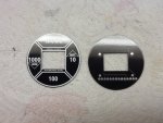
Anyway, the switches are fairly large copper pads on the "top" layer of the round board. There is a square hole for the OLED display. The board solder mask and silkscreen provide the color and legends, and along with the quartz cover disc prevent physical contact with the touch pads.
The touch pads are connected with tented vias to the "bottom" layer of the board, where there is a row of pads later soldered to a ribbon cable. Other than the bottom pads and four traces, the entire bottom layer is ground plane. I see no reason you couldn't use that layer for surface mount components (including the Picaxe) instead.
Rip