Reading the Sega Mega Drive (Genesis) & Amiga CD32 controllers
In the process of turning a Zeemote JS1 bluetooth games controller into a box that allows you to plug old ZX Spectrum / Sega / Amiga games controllers it to control games such as those on console emulators on your Android phone/tablet, I discovered that not all joysticks & joypads with the standard DB9 connector are wired the same.
There's a main standard pinout which applies to most sticks/pads. All controllers outputs are pulled to ground when triggered.
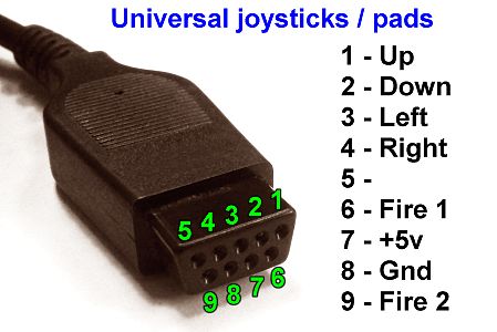
Few sticks/pads have 2 fire buttons such as the Sega Master System so only the first fire button is used, but the Mega Drive (Genesis) has a 3 button pad as standard and a 6 button one for even more control with fighting games etc.
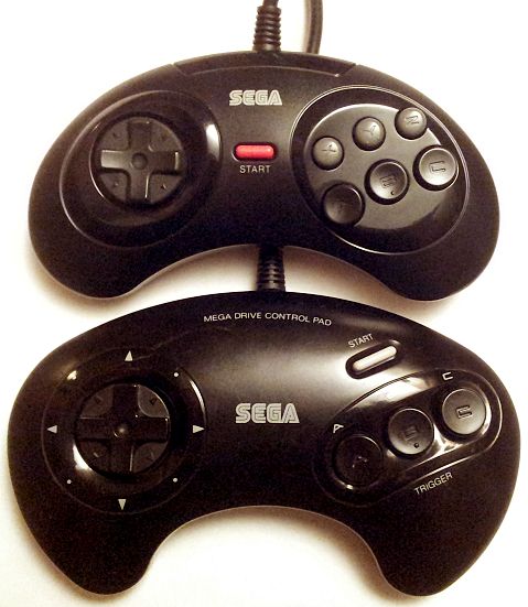
The 3 & 6 button Sega pads use a different pin for power and the main power becomes the select signal to trigger the controller to output the extra button states:
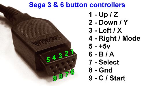
Using the information on these pages http://www.msarnoff.org/gen2usb/ & http://segaretro.org/Six_Button_Control_Pad_(Mega_Drive) I wrote code that allows a Picaxe to read all the Sega pad buttons which also detects wether a Sega Mega Drive / Genesis 3 or 6 button compatable controller is connected:
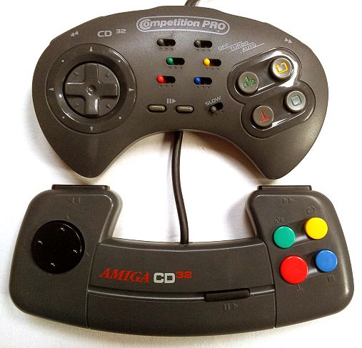
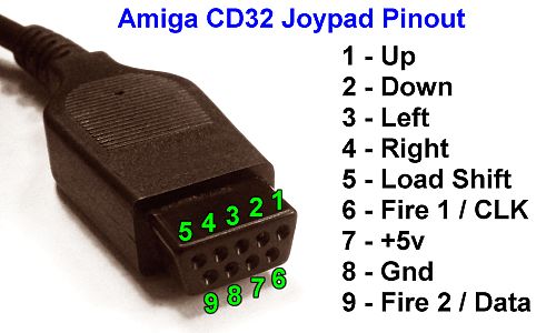
I also have an Amiga CD32 in a box somewhere which the controller pad also has the same connector type and extra buttons but uses a different shift method to read the extra buttons. I might have a stab at reading that pad too.
Lastly, just to confuse things further, the ZX Spectrum +2 & +3 have different pinout configurations for the joysticks, this was a move to attempt to sell you a whole new set of joysticks when you upgraded from the first generations of Spectrums, however adaptor cables quickly appeared and some joysticks came with two connectors so they would work on all Spectrums.
In the process of turning a Zeemote JS1 bluetooth games controller into a box that allows you to plug old ZX Spectrum / Sega / Amiga games controllers it to control games such as those on console emulators on your Android phone/tablet, I discovered that not all joysticks & joypads with the standard DB9 connector are wired the same.
There's a main standard pinout which applies to most sticks/pads. All controllers outputs are pulled to ground when triggered.
Few sticks/pads have 2 fire buttons such as the Sega Master System so only the first fire button is used, but the Mega Drive (Genesis) has a 3 button pad as standard and a 6 button one for even more control with fighting games etc.
The 3 & 6 button Sega pads use a different pin for power and the main power becomes the select signal to trigger the controller to output the extra button states:
Using the information on these pages http://www.msarnoff.org/gen2usb/ & http://segaretro.org/Six_Button_Control_Pad_(Mega_Drive) I wrote code that allows a Picaxe to read all the Sega pad buttons which also detects wether a Sega Mega Drive / Genesis 3 or 6 button compatable controller is connected:
Code:
' Read Sega Mega Drive (Genesis) 3-button & 6-button joypads
'
'
' Joystick pinout: (looking at joystick DB9 plug)
'
'    5 4 3 2 1
'     9 8 7 6
'
' 1 -    Up / Z
' 2 -  Down / Y
' 3 -  Left / Y
' 4 - Right / Mode
' 5 - +5v
' 6 -     B / A
' 7 - Select line
' 8 - Ground
' 9 -     C / Start
'
'
' Must run at 16mhz or faster to read 6-button pad.
' Button inputs must have pullup resistors or use internal pullup.
' Might not work with standard joysticks that have autofire or
'  other circuitry in them because their +5V line is DB9 pin 7
'  which is toggled to read the Sega pads.

#picaxe 20m2
#no_data

symbol DB9_1=pinc.3
symbol DB9_2=pinc.2
symbol DB9_3=pinc.1
symbol DB9_4=pinc.0
symbol DB9_6=pinb.6
symbol DB9_9=pinb.7
symbol DB9_7=b.5

symbol jup=b10
symbol jdown=b11
symbol jleft=b12
symbol jright=b13
symbol ja=b14
symbol jb=b15
symbol jc=b16
symbol jx=b17
symbol jy=b18
symbol jz=b19
symbol jstart=b20
symbol jmode=b21

setfreq m32

pullup on
pullup %0000111111000000

high DB9_7

do
 gosub ReadSegaGamepad
 sertxd("u=",#jup," d=",#jdown," l=",#jleft," r=",#jright," a=",#ja," b=",#jb," c=",#jc," x=",#jx," y=",#jy," z=",#jz," start=",#jstart," mode=",#jmode,cr,lf)
loop


ReadSegaGamepad:

 ' Read the standard buttons most controllers use
 jup=1-DB9_1
 jdown=1-DB9_2
 jleft=1-DB9_3
 jright=1-DB9_4
 jb=1-DB9_6
 jc=1-DB9_9

 low DB9_7

 ' Check to see if Sega joypad detected
 if DB9_3=0 and DB9_4=0 then

  ' Read in extra buttons on 3-button controller
  ja=1-DB9_6
  jstart=1-DB9_9

  ' Attempt to read in extra buttons on 6-button controller
  high DB9_7
  low DB9_7
  high DB9_7
  low DB9_7
  high DB9_7

  jx=1-DB9_3
  jy=1-DB9_2
  jz=1-DB9_1
  jmode=1-DB9_4

  low DB9_7
 endif

 high DB9_7
returnLastly, just to confuse things further, the ZX Spectrum +2 & +3 have different pinout configurations for the joysticks, this was a move to attempt to sell you a whole new set of joysticks when you upgraded from the first generations of Spectrums, however adaptor cables quickly appeared and some joysticks came with two connectors so they would work on all Spectrums.
Last edited:
")