Inverter circuit

ZOR

Senior Member
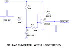
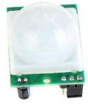
I am trying to invert the output from a PIR into a Picaxe input, because the normal PIR output goes high when triggered, but I want the opposite, go low when triggered. I want this arrangement so if the unit gets damaged it leaves a defaul high into the Picaxe

PIR.jpg

invert.jpg

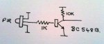
My problem is when I connect the output of the PIR inti the inverter circuit the PIR keeps cycling high/low. I found with a meter that the PIR output when high it's 3.27 volts, but when connected to my inverter circuit it drops to 1.75 volts. Am I doing something wrong?
 

jims

Senior Member
ZOR...I have a PIR (model HC-SR501) that looks like your unit, and I found that if the supply voltage is less then 4vdc, the PIR unit cycles ON/OFF continuously. You may want to see if this is what's happening with your unit.
JimS
 

ZOR

Senior Member
Thanks Jima. I had 4.7 volts on it. Maybe faulty unit. Bought 5 from China, 2 no life, other 3 doing this. First time had suspect items Ebay/China
 

Goeytex

Senior Member
If the supply voltage is OK then make sure the transistor is not backwards. With the leads pointing down and the flat side facing you, the emitter is on the right. This is reversed with 2N Series transistors where the emitter will be on the left.

If still no good then I would be tempted to use an op-amp or comparator to invert the signal due to the high impedance inputs.
 

Attachments

ZOR

Senior Member
Many thanks, no the transistors in the right round, used to send them on their next life in the past.

I had tried this before with a transistor before with no problem. Just curious why the devices output voltage drops so much when fed into the resistor/base of transistor.I did think of using an op-amp or comparator but took the simpler route. I might give it a try to see how that works Regards
 

eggdweather

Senior Member
You could invert the signal in software and once inverted apply the same logic as now, so no need for a hardware inversion.
 

erco

Senior Member
I did some head-scratching last week with a simple one-transistor amp that refused to work. Turns out I grabbed a P2N2222 transistor instead of a 2N2222. They look the same but have different pinouts.

+1 to Goeytex's IC inverter suggestion. In fact I just built ten of Goeytex's CP2012/74HC14 inverter USB programming adapters this week for a Picaxe class I'm teaching. Spreading the Picaxe gospel on this side of the pond.
 

ZOR

Senior Member
Thanks both.Would the software method involve 2 ports being used?
So easy to misread some part numbers, I really hate trying to read some IC type numbers, don't know why they make the lettering barely readable. Other hate is IC pins, they are always splayed out, having to be bent more vertical to go into sockets. I am going to try Goeytex's inverter. Regards
 

rossko57

Senior Member
Sounds odd; isn't this a security application? Wouldn't you want a damaged/disconnected PIR to cause an alarm?

There is probably an internal resistor to protect the PIR output, forming a potential divider with your resistor. At a guess, they've used 1K as well.
 

Jeremy Harris

Senior Member
Before doing anything else, just change the 1k resistor for something more sensible, like 10k or perhaps 22k. You don't need anything like 4mA of base current (which is roughly what the 1k resistor gives you), in fact you probably only need a few µA of base current. Change the 10k collector load to something like 100k, too, as you need very, very little current to pull a Picaxe input high, in the region of a few tens of nA at the most.

Doing this will reduce the load on the PIR unit and may well fix the problem.

Whilst typing this I've had another thought; does the PIR unit have a pull up resistor internally, or is it an open collector output? Might just be worth checking, as if it needs a pull up to work that may well be the cause of your problem.
 

ZOR

Senior Member
Thanks Jeremy, it's just for a small walkway, I know they have been widely sold, and in the past I never had problems.
I had a 10k instead of the 1k in the beginning and it did not always switch the transistor.

As far as specs go seen nothing to give electrical information. Just found an article showing almost the same device.
http://www.instructables.com/id/PIR-Motion-Sensor-Tutorial/step3/Connecting-to-your-PIR/

I am concerned I might be loading it's output seeing it's output voltage dropping when connecting to the 1k. Will try the 10k again and change collector resistor.
 

ZOR

Senior Member
I changed the base resistor to 10k and the collector resistor to 100k. The PIR output voltage is 3.27 volts. When connected to 1k dropped to 1.75 volts. Now with resistor changes my PIR connected has gone from 1.75 volts to 2.9 volts so it's not loading the PIR output so much now. The PIR seems happier now, so I will carry on trying it. Thanks again
 
Last edited:

techElder

Well-known member
ZOR, try connecting a 10K from PIR output to VCC. Then connect base resistance to PIR. I think that's what others were trying to say.
 

ZOR

Senior Member
Thanks Texasclodhopper. After reading Jeremy's ideas, because I was unaware of an internal pullup resistor I walked passed it. Working okay at the moment but maybe worth adding in.
 
Top