Capacitor and resistor to get high/low through optocoupler for 24VAC on/off?

lbenson

Senior Member
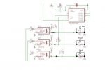
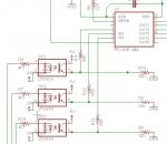
I'm monitoring a 24VAC line with a LTV-814 optocoupler. The picaxe (14M2) side of the optocoupler is 5V through a 680 Ohm resistor.

The logic level at the picaxe pin oscillates with the AC. Can I use a capacitor and resistor on the picaxe side of the optocoupler to get a logic level high when the AC is conducting, and low when not, and if so, what cap and resistor are appropriate?
 

Attachments

geoff07

Senior Member
You need both: the diode to turn the ac into dc half-cycles, and the cap to provide a reservoir for the pulsing dc to fill. Values depend on the frequency. You are creating a filter to get rid of the pulsing frequencies and leave you with smooth dc. 10uf across would be somewhere to start. The R needs to allow enough current in to keep the cap charged between half-cycles when the signal is present, allowing for the drain from the led. The C needs to have enough capacity to stay charged between half cycles, but not so much that it takes a long time to discharge when the signal goes away.
 

AllyCat

Senior Member
Hi,

The base-emitter junction of the phototransistor (in the optocoupler) will act as a diode, so the external diodes are not really necessary. However, the schematic in #2 should be fine. But personally, I'd be starting with a higher resistor value and lower capacitor value, perhaps 100 kohms and 1 uF.

To avoid potential "glitches" when an input switches on, it might be worth setting the 14M2 inputs to "Schmitt" (ST) using INPUTTYPE mask (then a capacitor nearer 100 nF may give a faster response).

Cheers, Alan.
 

hippy

Technical Support
Staff member
Depending on the application, what the control program has to do, and how responsive it needs to be, it may be possible to use the opto-interface as is without a capacitor by using PULSIN or COUNT to determine if there is AC present or not.

A quite responsive system could use interrupts -

Clear a flag then PAUSE 30
If AC is present it triggers an interrupt, sets the flag
After the PAUSE simply check the flag.
 

Goeytex

Senior Member
I fail to see why a diode is necessary. It is all + DC on the transistor side of the OPTO.

10uf seems a bit much and will likely cause a long delay before the level is low enough to signal a low to the input pin. Something like 80ms. If that is not too long then good. Otherwise a 1u should work ok and will give a high to low response time of about 10 ms.

But, as always, put your scope on it and do some measurements to confirm.
 

lbenson

Senior Member
Thanks for the responses. I had considered using the COUNT command, but wanted to know what the hardware solution would be. A cap around the pull-down resistor is easy. An 80ms response is fine--several seconds would be ok, since I only want to check on/off when "on" is likely to be a few minutes every several hours.

If 10K is too low to keep the signal from dropping, I'll increase it. Thanks for the suggestions regarding the response time.
 

Reloadron

Senior Member
The opto coupler you are using while designed for an AC input is best suited for circuits like a zero crossing detector. Note the opto couples has a pair of back to back emitting diodes at the input. Those emitters will conduct on alternate half cycles of the AC input. However when that AC input is crossing 0 Volts nothing is going on. Neither diode will be conducting. This amounts to pulses on the output and nothing will change that. The opto coupler is behaving exactly as it should. Sine wave in and pulses out.

1. You can do as hippy suggest and write code making those inputs a "missing pulse detector" in a sense so if no pulses are received for a time period (around 25 mSec) something happens.
2. You can full wave rectify the 24 VAC and filter it to drive the opto coupler.
3. You can find some small Miniature PC Board Relays having a 24 VAC coil (SPDT) and use those. The link is only an example.
4. You can build a missing pulse detector using a chip like a 555 (retriggerable one shot multivibrator). saving writing the interrupts in your code.
5. There are likely other options.

Personally I like #1 if it works for you.

You can also try as was suggested hanging a RC network off what you have but I don't see that working out very well.

Ron
 
Last edited:

eggdweather

Senior Member
I'm with hippy that using three pulsein commands one for each input to measure sequentially the pulse duration of ~8mS or 800 and as long as that number or more is detected, then there is AC present. There will be a maximum detection lag of 3x8mS (24mS) but for most applications that should be OK.
Assuming 60Hz (16.66mS per cycle)
start:
PULSEIN pin,1,channel1
PULSEIN pin,1,channel2
PULSEIN pin,1,channel3
IF channel1 <= 800 THEN
GOSUB warning_channel1_off
ENDIF
IF channel2 <= 800 THEN
GOSUB warning_channel2_off
ENDIF
IF channel3 <= 800 THEN
GOSUB warning_channel3_off
ENDIF
GOTO start

warning_channel1_off:
;do something
RETURN
 

hippy

Technical Support
Staff member
The disadvantage of PULSIN, when no pulse present, is it will timeout after 655ms at 4MHz with a zero result so can take up to one and a half seconds to read all three channels. COUNT can be done for shorter periods. At 16 or 32 MHz the timeouts should be more manageable.
 
Top