08M2 - ADC used to detect multiple independent digital inputs

AndreaACME

New Member
Hi all, I'm trying to have a few more digital input pins than there actually are available on the 08M2.
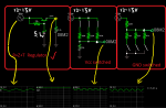
I'm aiming for 3 distinct "on/off type" inputs coming on the ADC pin (C.4) going through some kind of weighted resistor network. I've already tried the R-2R log ladder but it requires too accurate resistor values.

Has anyone already tried this or have a better suggestion?
I would rather code more than introduce ICs (comparators, etc) into the circuit.

Thanks
 

AndreaACME

New Member
What values should I use? I did not manage due to the strict tollerances and awkward values ....
When I read from ADC values are so similar in certain bits that I can't get a clear reading. Question: have you tried? Try it.

It could be that I'm doing something wrong in the wiring but it so simple it is not likely. Can you provide me with E12 set resistor values?

This is the log one:
http://upload.wikimedia.org/wikipedia/commons/thumb/4/41/R2r-ladder.png/420px-R2r-ladder.png
 

AllyCat

Senior Member
Hi,

It should be easy enough to do, but dpends if your "switches" are High/Low or Open/Closed. The ladder network (DAC) is really intended for High/Low signals (i.e. zero ohms to either a V1 or a V2 rail).

For Open/Closed switches a simple "weighted" set of series resistors, e.g. 10k, 20k (or 22k probably good enough) and 39k coupled into a "load" resistor (e.g. 10k) across the ADC pin to ground should work well enough. It's basically the method used for reading the Row/Columns of 3 x 4 or 4 x 4 matrix keypads into a single ADC pin.

Cheers, Alan.
 

AndreaACME

New Member
No it isn't, that is the DAC one.
By "log" I meant the logarithmic response DAC converter. It does not work in a linear fashion: counting in binary you will see the first LSB will be half the voltage already, not a seventh and all the rest of the vaules squash up in the top half of the rail voltage.

Due to the fact that I will be reading that voltage with the PICAXE ADC it will be linearly converted to a number. For the initial numbers it all works because there is a lot of space between the vaules and I can make some IF clauses with values between ranges. As soon as the last bits get used then all the values are so close that they are unusable; any minimal fluctuation in rail voltage power supply will make those values jump to very different numbers.

I hope I managed to explain what happens.
 
Last edited:

AndreaACME

New Member
Hi,

It should be easy enough to do, but dpends if your "switches" are High/Low or Open/Closed. The ladder network (DAC) is really intended for High/Low signals (i.e. zero ohms to either a V1 or a V2 rail).

For Open/Closed switches a simple "weighted" set of series resistors, e.g. 10k, 20k (or 22k probably good enough) and 39k coupled into a "load" resistor (e.g. 10k) across the ADC pin to ground should work well enough. It's basically the method used for reading the Row/Columns of 3 x 4 or 4 x 4 matrix keypads into a single ADC pin.

Cheers, Alan.
The switches I am using (n.o.) when pressed/activated allow the rail voltage (5V) to pass through the top binary resistors into the network: SW off = 0V from top, SW on = 5V from top (of the posted schematic).
As I mentioned to nick12ab, I don't get equally spaced values and I can't distinguish between bits when you get to MSBs.

With 100K, 220K, 470K ladder and a bottom load resistor of 47K (as you propose) I get these values from ADC (@5V supply): 0, 23, 44, 60, 82, 93, 103, 112
Same values with 5.2V supply rail yield: 0, 38, 69, 91, 116, 129, 140, 149

Do you see what I mean by fluctuations? I can't use the same code to read ranges from 5V and 5.2V

Thanks
 

AllyCat

Senior Member
Hi,

If you use the same supply rail for the switches and PICaxe supply, then you shouldn't get much variation (because the ADC normally uses its supply rail as reference).

Your measured variation between 5.0 and 5.2 volts is much larger than expected, something must be wrong. However, strictly, your (47k) load resistor should be 10k or less (as specified by Microchip for the ADC source impedance).

Cheers, Alan.
 

premelec

Senior Member
@AndreaACME - As AllyCat points out your READADC are ratiometric to the V+ supply - since you only have a "few" switches to sense you don't need to use anything fancy like R-2R - e.g. for 3 sw: Just take 3 resistors of different values and one resistor of, say, average of those values [all in the KOhm range to not draw much current]. put the avgR to V+ and ADC input - switch the other 3 Rs to V- ; either calculate or empirically determine the 8 output ratios from this voltage divider and have your program determine which switches are closed or open. When I do this sort of thing I usually put it in a spread sheet and check that the ratios are differing enough to easily discern what switches are on... It's evident that the switched resistors must be all different or you couldn't tell which switch with same value R is switched... another fun Ohm's Law problem.... It IS important that the switch ON resistances are low and consistent.
 
Last edited:

AndreaACME

New Member
@AllyCat - Yes I'm afraid I do have a great voltage variation which I have to deal with but if I manage to space things correctly it should still be possible to do.

I must admit that I only talked about a little piece of my project and - yes - I actually have to deal with high digital input voltages where a boolean 1 can range from min 12V to max 15V and I have scaled it down to 5V by means of a resistor divider (beforehand). The 0.2V variation I was talking about was just an example of slight variation. In reality I have to deal with 1V variation (12-15V = 4-5V after the voltage divider my bad; I should have mentioned that from the start.
Also Rossko57 was right, I DO have two different voltages for signals and Vcc for PicAxe. The latter is derived from the 12-15V with an additional 2.2K resistor in series with a 5.1V zener to ground.

Now based on Premelec's (and AllyCat) idea I will take the voltage divider and integrate it in the same network.
Resistors from bits will be as they were before 100K, 220K, 470K and the single 22K resistor to ground with a 5.1V zener in parallel just for protection against unexpected input high voltages overrange.

Thanks to all, I will try again to collect more values tomorrow with this new configuration (no R-2R network).
 

premelec

Senior Member
18k, 33k, 56k each switched to V- and one end of 22k that goes to V+ gives about 9 or more points spread out of 255 with all switches open... [READADC] 36 or more points difference on READADC10 - 1023
 
Last edited:

inglewoodpete

Senior Member
I would recommend that you replace the zener regulator with a low power regulator like the 78L05 or similar. This will need a couple a capacitors but your zener solution would need a capacitor to supress noise anyway.
 

inglewoodpete

Senior Member
A few hours later, after further thought.

Rather than add all those resistors etc to your project and many many hours developing and testing, it may be simpler to use a bigger PICAXE, like a 14M2 or 18M2. Also, you could configure the input switches in a matrix: (with a larger chip) 5 pins for 6 inputs (3x2); 6 pins for 9 inputs (3x3).
 

AllyCat

Senior Member
Hi,

I actually have to deal with high digital input voltages where a boolean 1 can range from min 12V to max 15V and I have scaled it down to 5V by means of a resistor divider (beforehand).

.... with a 5.1V zener in parallel just for protection against unexpected input high voltages overrange.
If I understand correctly, that's still not going to work. A resistor divider chain will only reduce the absolute voltage change, not the percentage variation, so you will still have "tolerance" issues. You need to stabilise each of your '1' levels individually. Perhaps the easiest way is to ensure that the middle point of each divider chain can always go slightly above the PICaxe supply rail and then "catch" each of these points with a (forward) diode to the supply rail. Then the lower resistor in each divider chain can provide your "binary weighted" value for the "DAC" to feed the input pin.

18k, 33k, 56k each switched to V- and one end of 22k that goes to V+
33k in parallel with 56k gives about 21k, so I prefer your 18k to the previous (edited) 22k. ;)

Unfortunately, the E12 resistor series doesn't have any exact 2:1 ratio values (E24 gives choices such as 10k/20k , 15k/30k , etc.). For only 3 switches you can probably get "near enough", but an easy trick would be to use 5 resistors of the same value (which also will likely be much closer matched than their nominal 5%, if manufactured at the same time). Typically use 22k, then two in parallel can give 11k and two in series 44k, to give a "perfect" 11k , 22k , 44k binary-weighted series.

Cheers, Alan.
 

AndreaACME

New Member
@inglewoodpete - Great input/tip for me. I agree that using R+Z is not a very stable solution, but I already have part of the circuit layed out, so I opted for adding a transistor (R+Z+T) to stabilize and provide more Vcc power. I have some construction limitations already for this circuit and I'm afraid I cannot choose to use another footprint for the IC; that means I'm stuck on a 8-DIP, I can't upgrade to 14-pin sorry, hence my quest to find a solution to having multiple inputs on a single pin. Nevertheless the idea of stabilizing is gladly acceptd; it will, no doubt, help.

@premelec - So what you suggest is to work upside-down? Switch to GND instead of switching from Vcc as I was? Is there a specific reason for this approach? At present I actually have it the other way round.
I also have to go back to reading classes because only now I realize that the 08M2 has a 10bit ADC .... I thought ADCs were all 8bit and identical (pin C.1-C.2-C.4) .... RTFM RTFM RTFM. Ok, lesson learned! That will greatly help too, thanks.
(EDITED) Actually I have tried it and I have a major issue with switching to GND: the voltage is not scaled anymore (no proper voltage divider) if the switches are all open I get 12-15V at input .... KABOOM PicAxe syndrome.Immagine.png
 
Last edited:

premelec

Senior Member
I think you are misunderstanding the READADC ratiometric situation - the resistors MUST be between V+ and V- ON the PICAXE - hence no more than 5volts. You can do other configurations but in any case the voltage will have to be regulated to get a meaningful reading on the READADC. My preference to switch to V- is only that I like one side of the switch at V- ... Your OP refers to more inputs from one pin... if these must be from a higher voltage rather than just showing a switch is on or off the situation is different... Also - note that the resistors must be stable for long term accuracy - metal film rather than carbon comp....
 
Last edited:

rossko57

Senior Member
Actually I have tried it and I have a major issue with switching to GND: the voltage is not scaled anymore (no proper voltage divider) if the switches are all open I get 12-15V at input .... KABOOM
But if your switches are going to ground (ground is common to Picaxe supply and the "12V" side, yes?), then you can feed the head of the resistor chain from the Picaxe supply rather than the "12V" supply.
 

AndreaACME

New Member
@rossko57 - You are right, it would be great if I could use the input as 5V and switch it, but that is not my case. I'm afraid I have voltages coming from another machinery which outputs 12-15V as a high value and 0V as a low (basically it shorts to GND). I have used that simple sketch just as an illustration purpouse not as a definitive schematic. In short: wish I could do that, but I can't.
I really need to convert that high voltage to low voltage first (as previous comments said) and then I will be able to work with them.

Still... I have tried making a little circuit with some switches to 15V just to see what values I get and 0, 16, 80, 91, 159, 164, 210, 213 is not bad except for the last two values which are too close. :(
I'm nearly there, just need to tweek the resistors a little more I guess...
 

premelec

Senior Member
You can use the higher voltage to feed the base of a transistor through a resistor to switch that resistor [tied to transistor collector] in and out of the ratiometric configuration. That simple circuit would effectively give you level conversion and maintain ratiometric situation. Part of your unstated situation is how stable the 15 volt source is... if it is really stable and the PICAXE V+ is also stable that simplifies your situation... If you use the transistor switch VbeSat will also affect your readings.
 

rossko57

Senior Member
If I've understood right, you want to look at incoming "logic levels" that may be at either 0V or some vague high voltage in the 12-15V area.
Block out the unwanted high voltage with a diode in each logic line. Now you can apply the blocked logic levels to a resistor network biased by the Picaxe +5V supply. Each link in the chain is either left to float naturally (because the high voltage is blocked by diode) or taken to ground. Output will not be influenced by the vagueness of the 12V ish source
 

AndreaACME

New Member
rossko57 & premelec are saying the same thing and I think you are right, I will have to normalize that high voltage somehow otherwise it will drive me nuts.
 

westaust55

Moderator
@AndreACME,

instead of a group of resistors (whioch will still take up space on a board and more difficult/complex to select suitable sizs), if you are adament that you wish to stay with the 08M2 rather than a larger PICAXE chip as suggested by InglewoodPete (post7)
then why not consider using a 74HC165 parallel to serial shift register chip.
Using 3 PICAXE IO pins you then have available 8 inputs.
Need more than 8 inputs then cascade on another 74HC165 chip to gain 16 inputs for use of the same three PICAXE IO pins.

Then use the bit-bashed code example found in the PICAXE manual 2 under the SHIFTIN command to clock the status of the pins into the PICAXE chip into 1 or 2 byte variables where you can test for values matching the used inputs on the 74HC165 chip.
 

edmunds

Senior Member
I have used both, I2C I/O expanders and resistor "ladder" for achieving precisely this. Actually, I'm using both methods in one project as I got sick and tired of adding more expanders at the count of 6 and I only needed 3 inputs or actually three states of the same input. The I/O expanders I have got to work for me are PCA9554 and PCA9555 series and I cannot complain. Reliable little buggers. You will find some code on the forum if you look for these.

For three inputs I have code like this

Code:
  readadc 6, helper3
  select case helper3
    case 0 to 64 : ModeFlag = 2                        'TLM not present or jumper not set
    case 65 to 128 : ModeFlag = 1                     'TLM present, set to yellow only mode (yellow jumper, high value resistor)
    case 129 to 196                                          'TLM present, for future use
    case 197 to 256 : ModeFlag = 0                   'TLM present, trafic lights in normal mode (green jumper, no resistor)
  end select
The idea is, there is an extra plug-in module for traffic light control with its own jumper setting for selecting operation mode. I do not remember resistor values at this point and don't have the schematics at hand, but the idea is, with intervals like this you do not need to be very precise at all. This could be adjusted to almost anything you have in your spare, odd resistors bin. Voltage fluctuations can move the value by 1 up or down, but should not be much more unless you are referencing your ADC to external voltage with adcsetup command and then you have to look for the problem elsewhere.

EDIT: Forgot to mention weak pull-up resistor. 2k should work.

Good luck,

Edmunds
 
Last edited:
Top