08M2 doesn't read DS18B20

npomeroy

Member
In my first foray into using the DS18B20 (to avoid calibrating thermistors and adding the necessary pots to the circuits) I am not getting any debug result. This is the simple test code
Code:
Main:

	let w0 = 450
	readtemp12 C.4,w1
	debug
	high C.1
	pause 20
	low C.1
	pause 50
	goto main
The LED on C.1 flickers at the expected rate without any delay that would be expected from the sensor processing (the "up to 750 ms" in the datasheet). The debug shows 450 for w0 and 0 for w1. When I removed the sensor and connected a 4.7K resistor between the data (orange) wire and ground, thus creating 4.7K / 4.7K voltage divider and changing the code to readadc C.4 I debugged the expected w1 = 124. There is 4.95v across the outer terminals of the sensor.
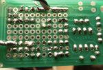
I've attached a PDF showing the board layout and some shots of the actual circuit.

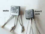
EDIT - the chip engraving is "Dallas / 18B20 / 1241C4 / +950AB"

View attachment Temp circuit 1Apr15.pdf

Regards
Nelson
 
Last edited:

eclectic

Moderator
Just tried this modification, on

AXE091 board.

Code:
Main:
 let w0 = 450
 
 readtemp12 C.4,w1
 b6 = w1 /16
 
 readtemp C.4,b5
 
 debug
 
 
; OR  sertxd (#b5, " ", #b6)

 high C.1
 pause 20
 low C.1
 pause 50
 goto main

Works fine.

Please check Manual 2 and your board wiring.

e
 

npomeroy

Member
Thanks Eclectic: I tried that code and still no change. I think the telling point is that there is no delay after the readtemp command: There is normally a processing time that delays the next program step but my LED keeps flashing at about the rate it does without a readtemp. On the other hand I tested the input with a readadc command and relevant wiring and it responded.
I've checked the commands, and I've checked the wiring but of course we all overlook things sometimes. I've never used the sertxt command am not sure how. I used that code and brought up a window under picaxe/terminal. 4800 baud. I got strings of oo in the output buffer but the input stayed blank.
 

Technical

Technical Support
Staff member
Dead sensor - if the sensor doesn't respond as expected on the 1-wire bus there won't be any delay.
 

npomeroy

Member
To try a different chip, I bought one of these little bricks (DS18B20 on a board) http://www.freetronics.com.au/products/temperature-sensor-module#.VRs_GvmUeSo
which include an on-board 4.7K resistor. I connnected it to Vcc, pin C.2, and ground and I get an normal reading, plus the LED flashes slow down.

THEN I deleted my 4.7K R from C.4-Vcc, and plugged in the brick into C.4 and it also works!

As I intend to build around 30 of these circuits, and the sensor needs to be part embedded in an matrix, I'm not going to buy a $20 brick for each one. So I think my next step will be to reinstate my pull up resistor, de-solder the chip that works from its board, and try it in my original configuration.

EDIT - continued
So the de-soldered chip on the original C.4 (with 4.7K R reinstated) did NOT work, but the same chip worked on C.2. Because I'd attached a 3-wire lead to C.2 without the pull-up R (because it was on-board the brick), when I reconnected the naked DS18B20 I placed a resistor between the legs of the chip itself. SO it seems there's something funny about my wiring on C.4 although I can't see anything wrong with it.
 
Last edited:

npomeroy

Member
So then I went back to my old chips and I can't get them to work, on the same connection as the new one. The new one is a bit wider. Do the markings mean anything to anybody?DS18B20.jpg
 

bpowell

Senior Member
You might want to measure your pull-up resistor with an Ohm meter and confirm it's 4700 Ohm.

Can you post a picture of the bottom of your PCB?
 
Last edited:

npomeroy

Member
You might want to measure your pull-up resistor with an Ohm meter and confirm it's 4700 Ohm.

Can you post a picture of the bottom of your PCB?
I can confirm the resistors are 4700 ohm. Note that with a different chip I got it working.bottom.jpg
 

npomeroy

Member
I note that various versions of the picaxe power supply specifications mention extra capacitors. Is it likely some chips are more demanding than others of a smooth supply? My ultimate source is 12v DC from an ATX computer PS, into an LM7805 with a 100uF electrolyte. The kit little capacitor I've placed in its normal place. I noted a circuit for using the same sensor for Arduino seemed to have low value cap between the sensor input and ground.
 

neiltechspec

Senior Member
Unlikely to be fake then.

I have never needed to add any caps to the 18b20 i/p, and I've used loads.

If on a very long cable run, then I have added a small electrolytic across the 18b20 supply pins.

Just a thought, have you tried running it off 3 AA cells or a known 5v supply, just in case it's a power problem.

Neil.
 

npomeroy

Member
Looking around, in NZ the price is around $5 or $10 each ($10 possibly Maxim vs $5 from "3rd party" manufacturers). Internationally there are plenty of suppliers from China (Alibaba) selling them for a few cents each. There seem to be Maxim, Microchip, Intec brands at least. I think it is not so much "fake" chips, as a variety of manufacturers. Maybe some vary in a subtle way that affects the Picaxe application? Maybe its possible my non-working batch of 4 had been damaged by electrostatics? They weren't supplied in anti-static bags.
 

rq3

Senior Member
I can confirm the resistors are 4700 ohm. Note that with a different chip I got it working.View attachment 18074
From the photo, I suspect you're chasing solder blobs. Wick it clean, and start fresh. And double check those surface mount 4.7K pull-ups. I'd be willing to bet one is cracked across the film. Sometimes open, sometimes not. Isn't common, but it happens.

Rip
 

npomeroy

Member
From the photo, I suspect you're chasing solder blobs. Wick it clean, and start fresh. And double check those surface mount 4.7K pull-ups. I'd be willing to bet one is cracked across the film. Sometimes open, sometimes not. Isn't common, but it happens.

Rip
No sorry. The chip that has tested good was removed from the little PCB so no surface mount components involved. I am able to attach various DS18B20 chips to my circuit (via three wires to a prototyping board). The one I removed from the little PCB is good: the other 4 are bad. The bad ones fail to impose any delay on an LED flicker loop, and register no data in that variable under debug. It's still marginally possible that something about my circuit is sub-optimal so that it works with some chips and not others, but I think it is more likely they are dud chips for whatever reason.
 

Technical

Technical Support
Staff member
You've already identified in the earlier photo that the dud DS18B20's are a different physical shape to the working one, so it is quite possible they are fakes and hence a waste of time. Try buying a new genuine DS18B20 from someone like Element14 in NZ and try that.
 

bpowell

Senior Member
I must have misread...I thought you have NEVER had a DS18b20 work on the C.4 pin...you HAVE had one work on the C.2 pin, provided you're using the "brick" board (i.e. the pullups on that board).

Why don't you take some of your suspected "Bad" sensors, and install them on the "Brick board" and see if they work there?
 

neiltechspec

Senior Member
On the subject of fakes, it is possible for even reputable suppliers to get caught out.

(Everybody tries to save money these days, even component suppliers).

Buy some from another supplier.

Neil.
 

npomeroy

Member
On the subject of fakes, it is possible for even reputable suppliers to get caught out.

(Everybody tries to save money these days, even component suppliers).

Buy some from another supplier.

Neil.
Yep, I've ordered another 4 from another local supplier. I expect to need around 36 and so am price conscious but may end up getting them from Element14 or RS Components who charge half as much again.

Out of interest: My "good" one is 4.62mm wide and the "dud" ones are 4.32 - 4.36mm wide. Anyone with a digital caliper (or whatever) like to measure some other good ones?
 
Last edited:
Top