vref+ confusion

frank2644

Member
I'm trying to setup VREF+ to 1.024 ref voltage on a 20x2 chip. In reading many threads on this subject I'm really confused.


The documentation seems to say that on a 20x2 ADC1 is used. I assume that means to connect the 1.024 ref voltage to the ADC1 pin. But then I see code examples using "readadc10, 1, w9". That seems to imply that the voltage you are measuring is on ADC1.


So my confusion boils down to two questions:

1. Which pin do I connect to the 1.024v reference voltage?

2. What ADC do I use for voltage measurements?

Thanks
Frank
 

hippy

Technical Support
Staff member
1. Which pin do I connect to the 1.024v reference voltage?
ADC1 ( Vref+, B.0, leg 18 ) is the external reference voltage input for the chip.

2. What ADC do I use for voltage measurements?
The ADC channel to which you have your analogue voltage connected, which can be any ADC channel other than ADC1 ( as that is already being used to input the reference voltage ).

It's not clear which examples you were looking at but you are correct it does not make too much sense to read ADC1 when that is being used as an external Vref+ input. It could however be that ADC1 is being used with an internal Vref+ connection, which would be entirely acceptable.

Which makes me wonder if you are actually wanting to connect an external reference voltage or wanting to use the internal voltage reference ?
 

Technical

Technical Support
Staff member

frank2644

Member
I think my problem is the software version of my chip. The link below talks about version c.0 having a problem and that's the chip I have. In the first post of that thread they are using adc channel 1 and maybe that's part of the problem that poster had. Anyway I think I have some newer chips that I can try.

http://www.picaxeforum.co.uk/archive/index.php/t-14210.html

Relative to the FVRsetup command I don't think that applies to the 20x2 chip.

Thanks everyone for the help.
 

frank2644

Member
Okay, I found a 20x2 with version c.3 firmware and everything worked well.

Per Technical's recommendation I changed the reference voltage to 2.048v although 1.024 would have worked a little better for me.
 

Goeytex

Senior Member
While "not recommended", I have found from experimentation that using 1.024 as ADC VREF+ works fine.

I cannot find anything in the 18F14k22 Datasheet that indicates using the FVR 1.024v for ADC VREF+ is not recommended.
 

hippy

Technical Support
Staff member
I cannot find anything in the 18F14k22 Datasheet that indicates using the FVR 1.024v for ADC VREF+ is not recommended.
In the 18F14K22 datasheet I have ( DS41365E, which seems to be the latest on Microchip's site ), page 353, table 25-8 (paraphrased) -

AD06 | VREF | Vref+ - Vref- | Min 1.8V | Max VDD | 1.8V <= Vref+ <= VDD+0.3V
 

Goeytex

Senior Member
Thanks Hippy,

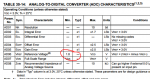
I overlooked that table. But I'm not confident that its intent is to say that 1.024 FVR should NOT be used as the ADC VREF+ and/or that this configuration is "not recommended". However ....Let's discuss the 18M2 PIC16F1847 instead since FVRSETUP and ADCCONFIG are are supported, and because the PIC 16F1847 has equivalent ADC specs. (DS40001453E-page 367 Table 25-8)

It is interesting that 1.8V is also the minimum supply voltage. So it makes sense to not use FVR 1.024 with a supply voltage less than 1.8V.. (Similar to using FVR 4.096 with a Supply < 5.0V ).

The Microchip Datasheet is void of any clear statements or warnings along the lines of "not recommended" and certainly not anything as strong as the statement in Picaxe Manual 2 that says:
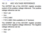
"Note that the 1.024V reference may not be used as the Vref+ of the ADC (only
2.048 or 4.096 may be used for this purpose)"
"May Not be used" ? Who came up with that statement?

I am not very confident that Microchip intended the table data to mean that 1.024 FVR "may not be used" or even "not recommended." , If it were that much of a problem then it seems to me that Microchip would have issued a clear warning or even eliminated the possibility. They did not.

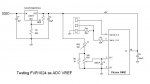
My testing on an 18M2 actually shows that it MAY be used and that it works quite well. Here's the setup and the test code.
My conclusion is that FVR1024 MAY be used As the ACD VREF+ as long as the impedance is not too high. In my test circuit VR2 is 3.4K when calibrated and VR1 with the shunt is 0 - 909R, so that's about 4.3K.

What did not work was a 10K Pot for VR1 and 34K for VR2. There simply was not enough current.

Here's the test code and schematic for anyone who cares to confirm/replicate my findings.

Code:
'===================
'File: FVR1024_ADC_TEST.BAS
'Author: "Goeytex" 
'===================

#Picaxe 18M2  'Firmware 2.A 
#No_Data
#Terminal 19200 

Setfreq M16
Pause 4000

INIT: 
FVRSETUP FVR1024 ' Fixed Voltage Reference @ 1.024V
ADCCONFIG %011   ' Use FVR for Vref +. OV for Vref -

MAIN:
Do
   ReadADC10 B.1,W0
   Sertxd (#W0,CR,LF)
   pause 1000

Loop
 

Attachments

Technical

Technical Support
Staff member
We have asked this question of Microchip before directly (ie directly to their technical staff). The 18M2 (1847) datasheet is also quite clear on the minimum Vref (see attached two screenshots below). 1.024V is below the minimum rated Vref (1.8V), so using 1.024V is quite a long way out of the manufacturers specification for the ADC operation.
 

Attachments

Goeytex

Senior Member
It's odd that the data published in the datasheet does not seem to stop FVR1024 as ADC VREF from working very nicely in the circuit I previously posted. I tested extensively and have used it in several projects with no problems at all.

I will continue to use it as needed regardless of the "official" line.
 

AllyCat

Senior Member
Hi,

I guess the key is the rather unqualified statement in the data sheet that : "The A/D conversion result never decreases with an increase in the input voltage and has no missing codes." With a successive approximation converter, that might not occur with the "major" steps, for example between %01 1111 1111 and %10 0000 0000, if the voltage steps become too small.

So under most operating conditions (particularly with 8-bit resolution) and with most values the ADC will probably work fine at lower voltages. But it's worth noting in the more recent "base PIC" data sheets (which have the Section 31 graphs populated), how poor the (potentially similar) comparator input offset voltage can become below about 1 volt common mode levels (Figure 31-58 in the 20M2 equivalent datasheet).

Cheers, Alan.
 
Top