how can i generate switching pulses for the 3 phase inverter using picaxe28x2
- Thread starter hareeshu
- Start date
fernando_g
Senior Member
The very first thing you must do, is to generate the timing diagram for the six pulses. Do you have that already?
eggdweather
Senior Member
Are you using a DC or AC motor and how are you intending to drive the motor, with a 3-phase bridge arrangement - usually with 6-PWM inputs?
You will need to generate three simultaneous PWM outputs separated by 120-degrees, something like (if P is ON and x is off:
PxxxxPxxxxPxxxxPxxxxPxxx
xxPxxxxPxxxxPxxxxPxxxxPx
xxxxPxxxxPxxxxPxxxxPxxxx
You will need to generate three simultaneous PWM outputs separated by 120-degrees, something like (if P is ON and x is off:
PxxxxPxxxxPxxxxPxxxxPxxx
xxPxxxxPxxxxPxxxxPxxxxPx
xxxxPxxxxPxxxxPxxxxPxxxx
I read an excellent article some years back on the NASA website which detailed how they generated a three phase supply for an experiment on the International Space Station.
They used a clock running at 300Hz (or six times the required output frequency). This fed into a series of SR (Set - Reset) latches triggered by a decade counter set to reset after six cycles. This gave the following outputs:
This results in three 50Hz square wave outputs (or clock/6) each with a 120 degree offset from the previous one.
I implemented this using a 555 timer, some SR latches (4027) a 4017 dacade counter and other logic to provide the reset pulse at the correct time in the sequence. The same could be done fairly easily using some logic within a PicAxe micro controller. I wish I'd had access to one at the time I made mine the hard way.
I wanted my output to be a (fairly good) 50Hz sine wave so filtered the square wave outputs and then them fed to three high power Op-Amps to provide a voltage of 20V Pk-Pk. We used this for demonstrating the power difference in circuits connected in a Delta or Star configuration using three lamps the students could wire up themselves. This worked very well, the difference in brightness between the wiring configurations instantly showed that Delta connections produced higher power outputs for the same supply potential. As all experiments took place at low voltages and low currents, there was much reduced risk to the students. We only had very limited three phase supplies available so couldn't use transformers.
They used a clock running at 300Hz (or six times the required output frequency). This fed into a series of SR (Set - Reset) latches triggered by a decade counter set to reset after six cycles. This gave the following outputs:
Code:
1=Output on 0=Output off

101010101010 (Clock = 6x output Frequency)
S     R      (SR latch one signals)
111111000000 (Phase one)
  S     R    (SR latch two signals)
001111110000 (Phase two)
    S     R  (SR latch three signals)
000011111100 (Phase three)
(Reset counter at this point then repeat)I implemented this using a 555 timer, some SR latches (4027) a 4017 dacade counter and other logic to provide the reset pulse at the correct time in the sequence. The same could be done fairly easily using some logic within a PicAxe micro controller. I wish I'd had access to one at the time I made mine the hard way.
I wanted my output to be a (fairly good) 50Hz sine wave so filtered the square wave outputs and then them fed to three high power Op-Amps to provide a voltage of 20V Pk-Pk. We used this for demonstrating the power difference in circuits connected in a Delta or Star configuration using three lamps the students could wire up themselves. This worked very well, the difference in brightness between the wiring configurations instantly showed that Delta connections produced higher power outputs for the same supply potential. As all experiments took place at low voltages and low currents, there was much reduced risk to the students. We only had very limited three phase supplies available so couldn't use transformers.
Last edited:
If using a 4017, did you need the latches? I'd have thought you could just have ORed together the appropriate trio of the 4017's outputs for each phase - either with a 4075 or just with diodes and a pulldown resistor. You might get a couple of tiny glitches in each square wave but your filtering would take care of that.
I like your diode idea. It seems promising on first thought so I might be tempted to agree with you there.
The idea was a modified version of the one that NASA had originally devised and I was pleased to make it work at all as a cleverer man than me (a Dr. in electronics) told me it wouldn't work!
The idea was a modified version of the one that NASA had originally devised and I was pleased to make it work at all as a cleverer man than me (a Dr. in electronics) told me it wouldn't work!
fernando_g
Senior Member
One only needs to Google "three phase inverter waveforms", for dozens of circuits to appear. The simplest uses a shift register and a couple of inverter gates.
All of these circuits however, are "180 degree conduction" pulses. They work perfectly well but have a significant amount of harmonics.
The most worrisome is the 5th, as it generates torque in the opposite direction of the motor's rotation. This will cause significant inefficiencies and motor overheating.
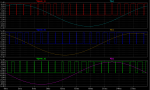
The better motor inverters generate SPWM waveforms, as shown in the attached image below. This would require a very large lookup table if using a Picaxe, which BTW was the original poster's request.
All of these circuits however, are "180 degree conduction" pulses. They work perfectly well but have a significant amount of harmonics.
The most worrisome is the 5th, as it generates torque in the opposite direction of the motor's rotation. This will cause significant inefficiencies and motor overheating.
The better motor inverters generate SPWM waveforms, as shown in the attached image below. This would require a very large lookup table if using a Picaxe, which BTW was the original poster's request.
Looking at that diagram; there appears to be 20 pulses per phase, 40 transitions, so 120 transitions in total. That would fit into a 120 byte EEPROM table and it's possibly less if transitions on multiple phases occur at the same time. A "delay this long then set outputs as this" byte pair could allow for a very simple program to generate what is required though one would have to calculate the data table.The better motor inverters generate SPWM waveforms, as shown in the attached image below. This would require a very large lookup table if using a Picaxe, which BTW was the original poster's request.
I thought the timing I posted could be very easily achieved with a PicAxe. The way I had to build mine was a very hard way of doing it, and I wish I'd had a PicAxe at the time. I hoped to inspire Hareeshu to decode the timing into a For..Next loop with a few nested If..Then statements that would produce the same outputs.One only needs to Google "three phase inverter waveforms", for dozens of circuits to appear. The simplest uses a shift register and a couple of inverter gates.
All of these circuits however, are "180 degree conduction" pulses. They work perfectly well but have a significant amount of harmonics.
The most worrisome is the 5th, as it generates torque in the opposite direction of the motor's rotation. This will cause significant inefficiencies and motor overheating.
The better motor inverters generate SPWM waveforms, as shown in the attached image below. This would require a very large lookup table if using a Picaxe, which BTW was the original poster's request.
View attachment 17979
If a sine wave output is needed at a high power output then things can get very complex, very quickly. To produce an AC supply from DC at 240V needs some very careful thought. Though Hareeshu did say that it was the switching pulses in the sequence that was what was all that was required.
premelec
Senior Member
For sine generation - search "magic sine" at www.tinaja.com...
fernando_g
Senior Member
Sure;@Fernando
Can you post the ASC file or link to the sim graphic?
Thanks
Goey
There a couple of things you should be aware of:
1) For the purpose of the study, and to make phase delay calculations simple, I arbitrarily chose a period of 30 msecs = 33.33Hz. For 50/60 Hz, you have to scale the timings
Code:
2) I also chose a simple 10X carrier ratio frequency. A higher carrier ratio will yield improved resolution, at the expense of many more data points. A lower carrier, the opposite is true.
3) I'm only showing the pulses for the top leg Mosfets. The bottom ones should be inverted with respect to the top.
fernando_g
Senior Member
For some reason, the "manage attachments" tool is not working....I just upgraded to this computer a few days ago, and I ignore if it is something wrong.
However, it will allow me to do it as simple text, copy it into notepad and change the extension to .ASC
Version 4
SHEET 1 880 680
WIRE 528 -48 528 -64
WIRE 528 -48 512 -48
WIRE 544 -48 528 -48
WIRE 512 -32 512 -48
WIRE 544 -32 544 -48
WIRE -400 0 -400 -16
WIRE -288 0 -320 0
WIRE 496 0 464 0
WIRE 656 16 656 0
WIRE 656 16 576 16
WIRE 496 32 432 32
WIRE 544 80 544 64
WIRE -400 96 -400 80
WIRE -400 96 -432 96
WIRE -288 96 -288 80
WIRE 512 96 512 64
WIRE 512 96 480 96
WIRE -432 112 -432 96
WIRE -400 128 -400 96
WIRE -288 128 -320 128
WIRE 544 160 544 144
WIRE 544 160 528 160
WIRE 560 160 544 160
WIRE 528 176 528 160
WIRE 560 176 560 160
WIRE 512 208 480 208
WIRE -400 224 -400 208
WIRE -400 224 -448 224
WIRE -288 224 -288 208
WIRE 672 224 672 208
WIRE 672 224 592 224
WIRE 512 240 448 240
WIRE -400 256 -432 256
WIRE -288 256 -320 256
WIRE 560 288 560 272
WIRE 528 304 528 272
WIRE 528 304 496 304
WIRE -400 352 -400 336
WIRE -288 352 -288 336
WIRE 544 368 544 352
WIRE 544 368 528 368
WIRE 560 368 544 368
WIRE 528 384 528 368
WIRE 560 384 560 368
WIRE 512 416 480 416
WIRE 672 432 672 416
WIRE 672 432 592 432
WIRE 512 448 448 448
WIRE 560 496 560 480
WIRE 528 512 528 480
WIRE 528 512 496 512
FLAG -432 112 0
FLAG -288 224 0
FLAG -288 352 0
FLAG -288 96 0
FLAG -400 -16 +5
FLAG 528 -64 +5
FLAG -448 224 -5
FLAG 480 96 -5
FLAG 544 80 0
FLAG -320 0 U
FLAG -320 128 V
FLAG -320 256 W
FLAG -400 352 0
FLAG -432 256 SW
FLAG 464 0 SW
FLAG 432 32 U
FLAG 656 0 PWM_A
FLAG 544 144 +5
FLAG 496 304 -5
FLAG 560 288 0
FLAG 480 208 SW
FLAG 448 240 V
FLAG 672 208 PWM_B
FLAG 544 352 +5
FLAG 496 512 -5
FLAG 560 496 0
FLAG 480 416 SW
FLAG 448 448 W
FLAG 672 416 PWM_C
SYMBOL Comparators\\LT1715 528 16 R0
SYMATTR InstName U1
SYMBOL voltage -400 -16 R0
WINDOW 123 0 0 Left 2
WINDOW 39 0 0 Left 2
SYMATTR InstName V1
SYMATTR Value 5
SYMBOL voltage -400 112 R0
WINDOW 123 0 0 Left 2
WINDOW 39 0 0 Left 2
SYMATTR InstName V2
SYMATTR Value 5
SYMBOL voltage -288 -16 R0
WINDOW 3 -70 -79 Left 2
WINDOW 123 0 0 Left 2
WINDOW 39 0 0 Left 2
SYMATTR InstName V3
SYMATTR Value SINE(0 4.6 33.3333333333333333333333333 0 0 0)
SYMBOL voltage -288 112 R0
WINDOW 3 -68 -175 Left 2
WINDOW 123 0 0 Left 2
WINDOW 39 0 0 Left 2
SYMATTR InstName V4
SYMATTR Value SINE(0 4.6 33.3333333333333333333333333 5m 0 0)
SYMBOL voltage -288 240 R0
WINDOW 3 -62 -274 Left 2
WINDOW 123 0 0 Left 2
WINDOW 39 0 0 Left 2
SYMATTR InstName V5
SYMATTR Value SINE(0 4.6 33.3333333333333333333333333 10m 0 0)
SYMBOL voltage -400 240 R0
WINDOW 3 -72 155 Left 2
WINDOW 123 0 0 Left 2
WINDOW 39 0 0 Left 2
SYMATTR InstName V6
SYMATTR Value PULSE(-4.7 4.7 0 0.75m 0.75m 0 1.5m)
SYMBOL Comparators\\LT1715 544 224 R0
SYMATTR InstName U2
SYMBOL Comparators\\LT1715 544 432 R0
SYMATTR InstName U3
TEXT -392 464 Left 2 !.tran 0 45m 15m
I'm not sure the PicAxe could manage the calculations required? It seems that "cos( 1*p1s )-cos( 1*p1e )+...+cos( 1*p7s )-cos( 1*p7e ) = ampl*pi/4" needs to be repeated for seven pulses, per quadrant, per cycle, per phase. Even with the maths co-processor, that would take some time.For sine generation - search "magic sine" at www.tinaja.com...
Once calculated into values they could be loaded into a look-up table but the article seems to suggest that extreme precision of the values is vital, with 12 bit resolution being required, either in hardware, or by splitting the 12 bit values to artificially re-create them within 8 bits.
Timing too looks like a problem, "Because of the exacting requirements of Magic Sinewaves, some ultra precise and non-mainstream programming techniques will usually prove of value. Timing and precision requirements can often end up unusually strict."
However, if the accuracy (and harmonic content) of the sine wave is not an issue, then the calculators on the website could be used to generate the table of values for creating the three phases required?
A very interesting read, thanks Premelec.
fernando_g
Senior Member
Yes you can, but I would be concerned about code latency. Something you need to check.
Having said that, I would do it with an external comparator. The LM339 is ubiquitous, inexpensive, and has 4 comparators in a 14 pin package.
Having said that, I would do it with an external comparator. The LM339 is ubiquitous, inexpensive, and has 4 comparators in a 14 pin package.