'drive 8574 based I2C lcd display in 4 bit mode
'D7- D4 of display mapped to P7-P4 of 8574
'changed pules enable line to single hi2cout command
'removed edelay constant
'removed other 'pause 10'delays between hi2cout commands
'works up to 32 MHz / remember to use I2CSLOW_32
'put BL = 1 after InitLcd so it won't be reset
#picaxe 08m2
'***************************************************************
'---------MAKE SURE LCD_ADR IS CORRECT--------------------------
'***************************************************************
'Symbol LCD_ADR = $40 'I2C address of lcd
Symbol LCD_ADR = %01111110 'I2C address of lcd
Symbol RSCMD = 0 ' Select Command register
Symbol RSDAT = 1 ' Select Data register
Symbol shadow = b0 'used for hi2cout shadow port
'change the following 4 symbols to match display
Symbol RS = bit0 ' bit0 of shadow register (0 = Command 1 = Data bit)
Symbol RD = bit1 ' bit1 of shadow register (0 = Write 1 = Read)
Symbol E = bit2 ' bit2 of shadow register (0 = Idle 1 = Active)
Symbol BL = bit3 ' bit3 of shadow register (backlight)
Symbol fetch = b4
Symbol char = b5
Symbol nibReg = b6
Symbol temp = b7
Symbol hunsDig = b8
Symbol tensDig = b9
Symbol onesDig = b10
Symbol counter = b11
'-------------------------------------------
'setfreq M32 -------------JTE Removed
Gosub InitLcd
main:
BL = 1 'backlight on
char = 1 'clear screen
gosub SendCmdByte
pause 20 'pause after clear screen
'Move to line 1
char = 128
Gosub SendCmdByte
For fetch = 6 TO 24 '"THANKS PICaxe FORUM" from eeprom
Read fetch,char
Gosub SendDataByte
Next
'Move to line 2
char = 192
Gosub SendCmdByte
For fetch = 26 To 44 '"I FINALLY FIGURED " from eeprom
Read fetch,char
Gosub SendDataByte
Next
'Move to line 3
char = 148
Gosub SendCmdByte
For fetch = 46 To 64 '"OUT THIS DISPLAY!!!" from eeprom
Read fetch,char
Gosub SendDataByte
Next
'Move to line 4
char = 212
Gosub SendCmdByte
For fetch = 66 To 84 '":) 03/04/2015 " from eeprom
Read fetch,char
Gosub SendDataByte
Next
End
InitLcd:
'make sure I2CSLOW_X matches clock speed
HI2cSetup I2CMASTER, LCD_ADR, I2CSLOW_32, I2CBYTE
shadow = %00110000 ' 8-bit mode
RS = RSCMD ' Send to Command register
RD = 0
temp = shadow
E = 1
HI2cOut(temp,shadow,temp ) ' Pulse E 1X
Pause 100
HI2cOut(temp,shadow,temp ) ' Pulse E 2X
Pause 100
HI2cOut(temp,shadow,temp ) ' Pulse E 3X
pause 100
shadow = %00100000 ' 4-bit mode
RS = RSCMD ' Send to Command register
RD = 0
temp = shadow
E = 1
HI2cOut(temp,shadow,temp ) ' Pulse E
E = 0
pause 100
'now we can use 4 bit interface for rest of initialization
char = $28 ' %00101000 %001LNF00 Display Format
Gosub SendInitCmdByte
char = $0C ' %00001100 %00001DCB Display On
Gosub SendInitCmdByte
char = $06 ' %00000110 %000001IS Cursor Move
Gosub SendInitCmdByte
char = 1 'Clear Screen
Gosub SendInitCmdByte
pause 20 'important beacuse last command was clear screen
Return 'InitialiseLcd
SendInitCmdByte:
Pause 60 ' Delay 15mS
SendCmdByte:
RS = RSCMD ' Send to Command register
RD = 0 ' Write to the display
SendDataByte:
'high nibble of char or instruction first
nibReg= char & %11110000 'high nibble of char
shadow = shadow & %00001111 'low nibble contains control signals
shadow = shadow | nibReg
temp = shadow
E = 1
HI2cOut(temp,shadow,temp ) ' Pulse E
E = 0
'lo nibble
nibReg = char * 16 'low nibble of char into high nibble of nibReg
shadow = shadow & %00001111 'low nibble contains control signals
shadow = shadow | nibReg
temp = shadow
E = 1
HI2cOut(temp,shadow,temp ) ' Pulse E
E = 0
RS = RSDAT ' Send default to Data register
Return 'SendDataByte , SendCmdByte , SendInitCmdByte
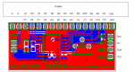
Eeprom 6, ("THANKS PICaxe FORUM")
Eeprom 26,("I FINALLY FIGURED ")
Eeprom 46,("OUT THIS DISPLAY!!!")
Eeprom 66,(":) 03/04/2015 ")
")