AXE029 connection

friis

Senior Member
Hi,
I think that I have destroyed 2 PICAXE 28X2 micro controllers by connecting the AXE027/AXE029 wrongly to the 28X2 and I would'nt like that to happen again I was wondering if somebody could advice me.

Seen from the bottom the connections of the AXE029 are as follows (with the jumper installed):
Code:
                            X
                            |
                             ----
                 X              |      X
  22 kOhm  |               |       |
                    -----        |       |
                         |       |       |
                X      X      X     X 

                        IN            0
                               OUT
Is that correct?
Which number terminal in the 28X2 should 0 go to?
Which number terminal in the 28X2 should OUT go to?
Which number terminal in the 28X2 should IN go to?

The PIXAXE terminals are numbered 1-14 and 15-28 starting from the upper left hand corner. Upper is where the indentation is.

I have ordered new 28X2 and I hope not to destroy those too.

torben
 
Last edited by a moderator:

friis

Senior Member
Hi,
I have to put in a character for space in the drawing of the AXE029:

.......................X
........................|
........................----
................X..........|.........X
22 kOhm....|..........|..........|
................ |..........|..........|
.................|..........|......... |
......X........X.........X........X

...............IN................... 0
.........................OUT

I hope that is OK.

torben
 

friis

Senior Member
Hi westaus55,
Can I connect 0 in AXE029 the general 0 or has it to be pin 8 - or does it not matter. I am pretty nervous.

torben
 

hippy

Technical Support
Staff member
It shouldn't matter as all 0V should be connected together. If used on breadboard it should only require plugging the AXE029 into the right place, setting the link, and all pins of the AXE029 should align with the 28X2 ...

Code:
                                    .----._.----.
                                   -| 1      28 |-
                                   -| 2      27 |-
         AXE029                    -| 3      26 |-
   .----------------.              -| 4      25 |-
  _|_.----.      oo |- N/C         -| 5      24 |-
 |   |    |   o  oo |- RXD ---- SI -| 6      23 |-
 |_ _|    |  |o| oo |- TXD ---- SO -| 7      22 |-
   | `----'  |o| oo |- 0V ----- 0V -| 8      21 |-
   `----------------'              -| 9      20 |-
              |                    -| 10     19 |-
       Fit link towards            -| 11     18 |-
          this side                -| 12     17 |-
                                   -| 13     16 |-
                                   -| 14     15 |-
                                    `-----------'
 

friis

Senior Member
Hi hippy,
It should all be clear now. Thank you very much.
But how can 5V damage the MC? I know that there is a 22 kOhm resister in the in-circuit, but still.
torben
 

westaust55

Moderator
But how can 5V damage the MC? I know that there is a 22 kOhm resister in the in-circuit, but still.
Not quite sure how you mean - in what context.

The AXE029 has two resistors 22 kIhm and 10 kOhm.
The 10 kOhm is a pull down to hold the serialIn line at 0 volts (0 logic state) until the PC indicates a new program is to be downloaded - holds the SerialIn pin low even when the AXE027 cable is disconnected from AXE029.
The 22 kOhm resistor is something of an "insurance" policy.
If the PICAXE is operating at 5 Volts and the AXE027 is used the resistor is not essential.
But if the PICAXE voltage is lower than th incoming voltage then the 22 kOhm resistor in conjunction with ESD diodes within the uC chip acts as a current limiter to prevent damage to the PICAXE chip.
The use/Ned originally came about with other programming cables such as the AXE026 which connected to the RE232 port (typically at rear or most) on the PC. RS-232 specs allow the data signals to swing between -25 volts and +25 volts and the resistor limits the current to around (25 - 5 / 22 k ==>) 1 mA which will not damage the PICAXE chip.


If you have the AXE029 connected incorrectly with say the jumper set for 18 but parts then there may be damage.

If you set a pin as an output and also apply a voltage of the opposite supply connection
Eg output set low and you connect +5V then that is like a short circuit at the PICAXE pin which will allow very high current flow and in a short time there will be at least some damage to the PICAXE chip.
 

friis

Senior Member
Hi westaust55,
I am confused.
In the paper that follows AXA029 hardware it mentions 18 and 28/40, But what
about 08, 14 and 20? It says about the 08 that you can place the jumper either
way (but breadboard wires are needed....). I have an experimenters board with 3
AXE029 adapted to 08/14/20, 18, 28/40. No breadboard wires are needed.
Is'nt it so, that as long as I make sure that TXD goes to OUT, RXD goes to
IN and 0 goes to 0 everything else is without importance?

torben
 

hippy

Technical Support
Staff member
I am confused.
In the paper that follows AXA029 hardware it mentions 18 and 28/40, But what about 08, 14 and 20? It says about the 08 that you can place the jumper either way (but breadboard wires are needed....). I have an experimenters board with 3 AXE029 adapted to 08/14/20, 18, 28/40. No breadboard wires are needed.
I am not sure of the above description but I think you are referring to the AXE091 which has three download sockets fitted and wired correctly for download into the three variously-sized chips which can be placed on the board; 8/14/20, 18 and 28/40.

There are not strictly "AXE029" interfaces though they are equivalent.

Is'nt it so, that as long as I make sure that TXD goes to OUT, RXD goes to IN and 0 goes to 0 everything else is without importance?
That is correct. Though power has to be connected ( multiple 0V pins on the chip must be connected together ), any reset pin needs a pull-up, and the 10K/22K interface must be present.

What the manual is saying is that you cannot just plug an actual AXE029 module into a breadboard or other circuit alongside a 8, 14 or 20-pin PICAXE chip and have it work as you can with the 18, 28 and 40-pin PICAXE chips.
 

hippy

Technical Support
Staff member
But how can 5V damage the MC? I know that there is a 22 kOhm resister in the in-circuit, but still.
Not quite sure how you mean - in what context.
I believe this relates to an issue over which friss contacted technical support. If I understand correctly; friis programmed two PICAXE 28X2 on an AXE091, moved them elsewhere, was unable to program then there using an AXE029, and when the PICAXE were moved back to the AX091 friss was still unable to program them.

I believe friss suspected the self-assembled AXE029 had damaged the PICAXE and asked if this were possible. On the information available at the time I believe the answer was along the lines of affirming it could be possible.

However; it is possible that the PICAXE are not damaged but are simply not responding to downloads and they need a Hard reset to achieve download.
 

friis

Senior Member
Hi hippy,
Thank you for your very thorough answers. I think a general description for all
micro controllers on a breadboard could be as follow:

1. If an AXE029 is used your drawing in #7 applies (pins no. 6, 7 and 8 for
28X2).
2. If an AXE029 is not used, the in-pin (nr. 6 - for 28X2) must be tied down
with a 10 kOhm resistor to 0V
3. There must always be a +5V and a 0V with a 100 nF capacitor connected (to
pins no. 20 and 19 respectively in case of the 28X2).

In case of 28X2 there must be 47 kOhm pull-up resistor as shown on page 35 in
the manual (not a 4k7 resistor). I assume that in general, if there is a reset
pin on the microcontroller, it must be pulled up with a 47 kOhm resistor.

The reset button is optional, but only relevant if there is a reset pin.

I have tried to do a hard reset - both ways and I assume thet the SW4 on the
experimenters' board is for the 28X2. I get the message: Searching for
hardware on COM3. and next: Error: Hardware not found on COM3!

But the progress-bar never appears. Do you know what is wrong?

torben
 

hippy

Technical Support
Staff member
The progress bar will not appear until the Programming Editor starts its download and it will not do that if it cannot find the hardware to download to. That is expected behaviour.

A 4K7 resistor as shown in the circuit diagrams is what we have always used for reset pull-up without any issues. When it is specified Microchip usually suggest between 1K and 10K.
 

westaust55

Moderator
@torben,
Some of the information you mention is already covered in PICAXE manual 1 in the minimum requirements as discussed for each chip.
For the 28 pin PICAXE chips see page 34.
http://www.picaxe.com/docs/picaxe_manual1.pdf#page34

The need for a generalised statement elsewhere could lead to confusion as there would be a need for various if... Then statement.
Ie if there is a reset pin then use a 4k7 Ohm pull up resistor on this pin.
 

friis

Senior Member
Hi hippy,
I assume that the fact that the progress-bar does not appear means that the 28X2 is destroyed.
I have noted that the pull-down resistor is 4.7 kOhm.
Thank you very much.
torben
 

friis

Senior Member
Hi westaustr55,
I have noted that the pull-up resistor is 4.7 kOhm.
Thank you very much.
torben
 

hippy

Technical Support
Staff member
I assume that the fact that the progress-bar does not appear means that the 28X2 is destroyed.
The "hardware not found" message indicates Programming Editor is not able to communicate with the PICAXE. There can be a number of reasons for that and it does not necessarily mean the PICAXE has been destroyed.
 

rossko57

Senior Member
To expand with a for-example, it is possible to have a Picaxe loaded with a user program which (inadvertently or deliberately) causes it to ignore the programming pin.
There is a special procedure to overcome this gotcha, called "hard reset". Worth trying several times before condemning a chip.
 

friis

Senior Member
Hi hippy and rossko57,
After waiting 2 weeks I got 2 28X2 - and had the same experience: I loaded the
pgm in once in the experimenters board, then installed it in the breadboard.
And then I could'nt load the pgm in again. But then I got in the experimenters
board:

1. Clicked the "Program"
2. Searching for hardware on COM3
3. Pressed the reset button
4. Downloading program
5. Downloading program/table
6. Downloading data
7. PASS - programmed PICAXE-28X2 (40X2) vB.3 successfully

Everything looked normal until I pressed the reset button to start the pgm when
I got nonsense in the Serial Terminal window. It should have produced "Main -
sun",......

It looks as if a nonsense pgm has been loaded into the 28X2.

Can anyone help?

torben
 

friis

Senior Member
Hi eclectic,
Here it is:
Code:
#PICAXE 28X2
#Terminal 4800

symbol dataOK = b0
symbol data1 = b1
symbol data2 = b2
symbol data3 = b3
symbol data4 = b4
symbol data5 = b5
symbol data6 = b6
symbol data7 = b7
symbol data8 = b8
symbol data21 = b9
symbol data22 = b10
symbol data23 = b11
symbol data24 = b12
symbol data25 = b13
symbol data26 = b14
symbol data27 = b15
symbol data28 = b16
symbol pump = b17
symbol flash = b18
symbol dataone = b19
symbol datatwo = b20
symbol limittime = b21
symbol counter = b22
symbol test = b23

symbol data1time = w12
symbol data2time = w13
symbol data3time = w14
symbol data4time = w15
symbol data5time = w16
symbol data6time = w17
symbol data7time = w18
symbol data8time = w19


MAIN:		
            sertxd ("AAAAAAAAAA"):dataOK = 0
		pump = 0
		data21 = 0:data22 = 0: data23 = 0: data24 = 0: data25 = 0: data26 = 0: data27 = 0: data28 = 0
		dataone = 0:datatwo = 0:counter = 0:test = 1
		settimer t1s_4
		
		if test = 1 then
			sertxd (cr,lf,"Main - Sun",cr,lf)
		endif
	
BEGIN:	DO
			if test = 1 then
				sertxd ("Begin - ####################",cr,lf)
			endif
			
			if timer < 600 and data1time > 64935 then    ;zero data21 after min. 10 min.
				data21 = 0
			else 
				limittime = data1time + 600
				if timer > limittime then
					data21 = 0
				endif
			endif
			
			if timer < 600 and data2time > 64935 then    
				data22 = 0
			else 
				limittime = data2time + 600
				if timer > limittime then
					data22 = 0
				endif
			endif
				
			if timer < 600 and data3time > 64935 then
				data23 = 0
			else 
				limittime = data3time + 600
				if timer > limittime then
					data23 = 0
				endif
			endif
		
			if timer < 600 and data4time > 64935 then
				data24 = 0
			else 
				limittime = data4time + 600
				if timer > limittime then
					data24 = 0
				endif
			endif
			
			if timer < 600 and data5time > 64935 then
				data25 = 0
			else 
				limittime = data5time + 600
				if timer > limittime then
					data25 = 0
				endif
			endif
			
			if timer < 600 and data6time > 64935 then
				data26 = 0
			else 
				limittime = data6time + 600
				if timer > limittime then
					data26 = 0
				endif
			endif
			
			if timer < 600 and data7time > 64935 then
				data27 = 0
			else 
				limittime = data7time + 600
				if timer > limittime then
					data27 = 0
				endif
			endif
			
			if timer < 600 and data8time > 64935 then
				data28 = 0
			else 
				limittime = data8time + 600
				if timer > limittime then
					data28 = 0
				endif
			endif
			
			if test = 1 then
				sertxd ("data21 to data28 zeroed",cr,lf)
			endif
			
			high A.1
			pause 500                                    ;flash
			low A.1
			rfin C.4,data1,data2,data3,data4,data5,data6,data7,data8
									
			if test = 1 then			
				dataone = dataone + 1    ;dataone = 1: reception, dataone = 2: transmission of receipt
				datatwo = datatwo + 1    ;datatwo = 1: start of unit 1, starttwo = 2: shut down of unit 1, datatwo = 3: start of unit 3.........
							
				if datatwo = 9 then
					datatwo = 1
				endif
				
				counter = counter + 1    ;introduce error in receptions or receipts
				
				if counter = 65300 then     
					data3 = 3         ;error - if applicable
					counter = 0
				else
					data3 = datatwo
				endif
				
				;data1=dataone:data2=datatwo:data4=datatwo:data5=datatwo:data6=datatwo:data7=datatwo:data8=datatwo
										
				sertxd ("Received: ",#data1,#data2,#data3,#data4,#data5,#data6,#data7,#data8,cr,lf)
			endif
						
			if data1 < 1 OR data1 > 2 then goto ERROR1   ;check validity
						
			if data2 < 1 OR data2 > 8 then goto ERROR2   ;check validity
			
			if data2 = data3 then                        ;check all data alike
				dataOK = dataOK + 1
			endif
			if data2 = data4 then
				dataOK = dataOK + 1
			endif
			if data2 = data5 then
				dataOK = dataOK + 1
			endif
			if data2 = data6 then
				dataOK = dataOK + 1
			endif
			if data2 = data7 then
				dataOK = dataOK + 1
			endif
			if data2 = data8 then
				dataOK = dataOK + 1
			endif
			
			if dataOK < 6 then goto ERROR3                ;not all data alike
			
			dataOK = 0                                   
			
			if test = 1 then
				sertxd ("Data OK",cr,lf)
			endif			
			
			high C.2
			pause 50
			rfout C.3,(2,data2,data3,data4,data5,data6,data7,data8)   ;answer OK - 2 indicates transmission originating from receiver
			low C.2
			high A.1
			pause 500                                     ;flash
			low A.1
			
			if test = 1 then
				dataone = dataone + 1
				;data1=dataone:data2=datatwo:data3=datatwo:data4=datatwo:data5=datatwo:data6=datatwo:data7=datatwo:data8=datatwo
				sertxd ("Answered data OK: ",#data1,#data2,#data3,#data4,#data5,#data6,#data7,#data8,cr,lf)
				
				if dataone = 2 then
					dataone = 0
				endif
				if datatwo = 8 then
					datatwo = 0
				endif
			endif
			
			If data2 = 1 then                   ;start valve and pump from satelite no. 1
				if data2 = data21 then        ;bypass repeat input
					goto begin
				else
					data21 = data2          ;keep data for check of repeat
					high B.0                ;open valve no. 1
					pause 500
					low B.0
					high A.0                ;start pump
					pump = pump + 1         ;keep check on how many have started the pump
					data1time = timer   
					if test = 1 then
						sertxd ("Unit 1 start",cr,lf)
					endif
				endif
			elseif data2 = 2 then               ;shut down valve and pump from satelite no. 1
				if data2 = data22 then
					goto begin
				else
					data22 = data2
					high B.1                ;shut valve no. 1
					pause 500
					low B.1        
					pump = pump - 1         ;check number of times the pump has been started
					if pump = 0 OR pump = 255 then        ;shut pump if this was the last
						low A.0
					endif
					data2time = timer   
					if test = 1 then
						sertxd ("Unit 1 stop",cr,lf)
					endif
				endif
			elseif data2 = 3 then
				if data2 = data23 then
					goto begin
				else
					data23 = data2
					high B.2
					pause 500
					low B.2
					high A.0
					pump = pump + 1
					data3time = timer  
					if test = 1 then
						sertxd ("Unit 2 start",cr,lf)
					endif
				endif
			elseif data2 = 4 then
				if data2 = data24 then
					goto begin
				else
					data24 = data2
					high B.3
					pause 500
					low B.3
					pump = pump - 1
					if pump = 0 OR pump = 255 then        
						low A.0
					endif
					data4time = timer
					if test = 1 then
						sertxd ("Unit 2 stop",cr,lf)
					endif
				endif
			elseif data2 = 5 then
				if data2 = data25 then
					goto begin
				else
					data25 = data2
					high B.4
					pause 500
					low B.4
					high A.0
					pump = pump + 1
					data5time = timer
					if test = 1 then
						sertxd ("Unit 3 start",cr,lf)
					endif
				endif
			elseif data2 = 6 then
				if data2 = data26 then
					goto begin
				else
					data26 = data2
					high B.5
					pause 500
					low B.5
					pump = pump - 1
					if pump = 0 OR pump = 255 then
						low A.0
					endif
					data6time = timer
					if test = 1 then
						sertxd ("Unit 3 stop",cr,lf)
					endif
				endif
			elseif data2 = 7 then
				if data2 = data27 then
					goto begin
				else
					data27 = data2
					high B.6
					pause 500
					low B.6
					high A.0
					pump = pump + 1
					data7time = timer
					if test = 1 then
						sertxd ("Unit 4 start",cr,lf)
					endif
				endif
			elseif data2 = 8 then
				if data2 = data28 then
					goto begin
				else
					data28 = data2
					high B.7
					pause 500
					low B.7
					pump = pump - 1
					if pump = 0 OR pump = 255 then
						low A.0
					endif
					data8time = timer
					if test = 1 then
						sertxd ("Unit 4 stop",cr,lf)
					endif
				endif
			endif
			
		Loop

ERROR1:	if test = 1 then
			sertxd ("ERROR1",cr,lf)
		endif
		
		flash = 0
		do
			flash = flash + 1
			high A.1
			pause 500                                    ;flash
			low A.1
			pause 500
		loop while flash < 11	
		
		dataOK = 0
		dataone = 0
		goto BEGIN
ERROR2:	if test = 1 then
			sertxd ("ERROR2",cr,lf)
		endif
		
		flash = 0
		do
			flash = flash + 1
			high A.1
			pause 500                                    ;flash
			low A.1
			pause 500
		loop while flash < 11	
		
		dataOK = 0
		dataone = 0
		goto BEGIN
ERROR3:	if test = 1 then
			sertxd ("ERROR3",cr,lf)
		endif
		
		flash = 0
		do
			flash = flash + 1
			high A.1
			pause 500                                    ;flash
			low A.1
			pause 500
		loop while flash < 11	
		
		dataOK = 0
		dataone = 0
		goto BEGIN
torben
 
Last edited by a moderator:

friis

Senior Member
Hi eclectic,
Here is a better one:

Code:
#PICAXE 28X2
#Terminal 4800

symbol dataOK = b0
symbol data1 = b1
symbol data2 = b2
symbol data3 = b3
symbol data4 = b4
symbol data5 = b5
symbol data6 = b6
symbol data7 = b7
symbol data8 = b8
symbol data21 = b9
symbol data22 = b10
symbol data23 = b11
symbol data24 = b12
symbol data25 = b13
symbol data26 = b14
symbol data27 = b15
symbol data28 = b16
symbol pump = b17
symbol flash = b18
symbol dataone = b19
symbol datatwo = b20
symbol limittime = b21
symbol counter = b22
symbol test = b23

symbol data1time = w12
symbol data2time = w13
symbol data3time = w14
symbol data4time = w15
symbol data5time = w16
symbol data6time = w17
symbol data7time = w18
symbol data8time = w19


MAIN:		
            sertxd ("AAAAAAAAAA"):dataOK = 0
		pump = 0
		data21 = 0:data22 = 0: data23 = 0: data24 = 0: data25 = 0: data26 = 0: data27 = 0: data28 = 0
		dataone = 0:datatwo = 0:counter = 0:test = 1
		settimer t1s_4
		
		if test = 1 then
			sertxd (cr,lf,"Main - Sun",cr,lf)
		endif
	
BEGIN:	DO
			if test = 1 then
				sertxd ("Begin - ####################",cr,lf)
			endif
			
			if timer < 600 and data1time > 64935 then    ;zero data21 after min. 10 min.
				data21 = 0
			else 
				limittime = data1time + 600
				if timer > limittime then
					data21 = 0
				endif
			endif
			
			if timer < 600 and data2time > 64935 then    
				data22 = 0
			else 
				limittime = data2time + 600
				if timer > limittime then
					data22 = 0
				endif
			endif
				
			if timer < 600 and data3time > 64935 then
				data23 = 0
			else 
				limittime = data3time + 600
				if timer > limittime then
					data23 = 0
				endif
			endif
		
			if timer < 600 and data4time > 64935 then
				data24 = 0
			else 
				limittime = data4time + 600
				if timer > limittime then
					data24 = 0
				endif
			endif
			
			if timer < 600 and data5time > 64935 then
				data25 = 0
			else 
				limittime = data5time + 600
				if timer > limittime then
					data25 = 0
				endif
			endif
			
			if timer < 600 and data6time > 64935 then
				data26 = 0
			else 
				limittime = data6time + 600
				if timer > limittime then
					data26 = 0
				endif
			endif
			
			if timer < 600 and data7time > 64935 then
				data27 = 0
			else 
				limittime = data7time + 600
				if timer > limittime then
					data27 = 0
				endif
			endif
			
			if timer < 600 and data8time > 64935 then
				data28 = 0
			else 
				limittime = data8time + 600
				if timer > limittime then
					data28 = 0
				endif
			endif
			
			if test = 1 then
				sertxd ("data21 to data28 zeroed",cr,lf)
			endif
			
			high A.1
			pause 500                                    ;flash
			low A.1
			rfin C.4,data1,data2,data3,data4,data5,data6,data7,data8
									
			if test = 1 then			
				dataone = dataone + 1    ;dataone = 1: reception, dataone = 2: transmission of receipt
				datatwo = datatwo + 1    ;datatwo = 1: start of unit 1, starttwo = 2: shut down of unit 1, datatwo = 3: start of unit 3.........
							
				if datatwo = 9 then
					datatwo = 1
				endif
				
				counter = counter + 1    ;introduce error in receptions or receipts
				
				if counter = 65300 then     
					data3 = 3         ;error - if applicable
					counter = 0
				else
					data3 = datatwo
				endif
				
				;data1=dataone:data2=datatwo:data4=datatwo:data5=datatwo:data6=datatwo:data7=datatwo:data8=datatwo
										
				sertxd ("Received: ",#data1,#data2,#data3,#data4,#data5,#data6,#data7,#data8,cr,lf)
			endif
						
			if data1 < 1 OR data1 > 2 then goto ERROR1   ;check validity
						
			if data2 < 1 OR data2 > 8 then goto ERROR2   ;check validity
			
			if data2 = data3 then                        ;check all data alike
				dataOK = dataOK + 1
			endif
			if data2 = data4 then
				dataOK = dataOK + 1
			endif
			if data2 = data5 then
				dataOK = dataOK + 1
			endif
			if data2 = data6 then
				dataOK = dataOK + 1
			endif
			if data2 = data7 then
				dataOK = dataOK + 1
			endif
			if data2 = data8 then
				dataOK = dataOK + 1
			endif
			
			if dataOK < 6 then goto ERROR3                ;not all data alike
			
			dataOK = 0                                   
			
			if test = 1 then
				sertxd ("Data OK",cr,lf)
			endif			
			
			high C.2
			pause 50
			rfout C.3,(2,data2,data3,data4,data5,data6,data7,data8)   ;answer OK - 2 indicates transmission originating from receiver
			low C.2
			high A.1
			pause 500                                     ;flash
			low A.1
			
			if test = 1 then
				dataone = dataone + 1
				;data1=dataone:data2=datatwo:data3=datatwo:data4=datatwo:data5=datatwo:data6=datatwo:data7=datatwo:data8=datatwo
				sertxd ("Answered data OK: ",#data1,#data2,#data3,#data4,#data5,#data6,#data7,#data8,cr,lf)
				
				if dataone = 2 then
					dataone = 0
				endif
				if datatwo = 8 then
					datatwo = 0
				endif
			endif
			
			If data2 = 1 then                   ;start valve and pump from satelite no. 1
				if data2 = data21 then        ;bypass repeat input
					goto begin
				else
					data21 = data2          ;keep data for check of repeat
					high B.0                ;open valve no. 1
					pause 500
					low B.0
					high A.0                ;start pump
					pump = pump + 1         ;keep check on how many have started the pump
					data1time = timer   
					if test = 1 then
						sertxd ("Unit 1 start",cr,lf)
					endif
				endif
			elseif data2 = 2 then               ;shut down valve and pump from satelite no. 1
				if data2 = data22 then
					goto begin
				else
					data22 = data2
					high B.1                ;shut valve no. 1
					pause 500
					low B.1        
					pump = pump - 1         ;check number of times the pump has been started
					if pump = 0 OR pump = 255 then        ;shut pump if this was the last
						low A.0
					endif
					data2time = timer   
					if test = 1 then
						sertxd ("Unit 1 stop",cr,lf)
					endif
				endif
			elseif data2 = 3 then
				if data2 = data23 then
					goto begin
				else
					data23 = data2
					high B.2
					pause 500
					low B.2
					high A.0
					pump = pump + 1
					data3time = timer  
					if test = 1 then
						sertxd ("Unit 2 start",cr,lf)
					endif
				endif
			elseif data2 = 4 then
				if data2 = data24 then
					goto begin
				else
					data24 = data2
					high B.3
					pause 500
					low B.3
					pump = pump - 1
					if pump = 0 OR pump = 255 then        
						low A.0
					endif
					data4time = timer
					if test = 1 then
						sertxd ("Unit 2 stop",cr,lf)
					endif
				endif
			elseif data2 = 5 then
				if data2 = data25 then
					goto begin
				else
					data25 = data2
					high B.4
					pause 500
					low B.4
					high A.0
					pump = pump + 1
					data5time = timer
					if test = 1 then
						sertxd ("Unit 3 start",cr,lf)
					endif
				endif
			elseif data2 = 6 then
				if data2 = data26 then
					goto begin
				else
					data26 = data2
					high B.5
					pause 500
					low B.5
					pump = pump - 1
					if pump = 0 OR pump = 255 then
						low A.0
					endif
					data6time = timer
					if test = 1 then
						sertxd ("Unit 3 stop",cr,lf)
					endif
				endif
			elseif data2 = 7 then
				if data2 = data27 then
					goto begin
				else
					data27 = data2
					high B.6
					pause 500
					low B.6
					high A.0
					pump = pump + 1
					data7time = timer
					if test = 1 then
						sertxd ("Unit 4 start",cr,lf)
					endif
				endif
			elseif data2 = 8 then
				if data2 = data28 then
					goto begin
				else
					data28 = data2
					high B.7
					pause 500
					low B.7
					pump = pump - 1
					if pump = 0 OR pump = 255 then
						low A.0
					endif
					data8time = timer
					if test = 1 then
						sertxd ("Unit 4 stop",cr,lf)
					endif
				endif
			endif
			
		Loop

ERROR1:	if test = 1 then
			sertxd ("ERROR1",cr,lf)
		endif
		
		flash = 0
		do
			flash = flash + 1
			high A.1
			pause 500                                    ;flash
			low A.1
			pause 500
		loop while flash < 11	
		
		dataOK = 0
		dataone = 0
		goto BEGIN
ERROR2:	if test = 1 then
			sertxd ("ERROR2",cr,lf)
		endif
		
		flash = 0
		do
			flash = flash + 1
			high A.1
			pause 500                                    ;flash
			low A.1
			pause 500
		loop while flash < 11	
		
		dataOK = 0
		dataone = 0
		goto BEGIN
ERROR3:	if test = 1 then
			sertxd ("ERROR3",cr,lf)
		endif
		
		flash = 0
		do
			flash = flash + 1
			high A.1
			pause 500                                    ;flash
			low A.1
			pause 500
		loop while flash < 11	
		
		dataOK = 0
		dataone = 0
		goto BEGIN
torben
 

hippy

Technical Support
Staff member
The default baud rate of SERTXD for an X2 is 9600 baud but your #TERMINAL is setting the terminal's baud rate to 4800; that will be why the display does not show what you expect.

It would also make sense to download simpler programs when testing everything is working, for example -

Code:
#Picaxe 28X2
#Terminal 9600
Do
  SerTxd( "Working ", #w0, CR, LF )
  w0 = w0 + 1
  Pause 1000
Loop
 

friis

Senior Member
Hi hippy,
After using your pgm and using 9600 I can make it work using a hard reset every time I load the pgm.
Thank you very much.
torben
 

friis

Senior Member
Hi,
I have 2 pgms:
Code:
	  #Picaxe 14m2
	  #Terminal 4800
        
 main: 	high B.3
		pause 500                                    ;flash
		low B.3
		sertxd (cr,lf,"AA")
		rfout B.5,(1,1,1,1,1,1,1,1)                  ;call for water - data1 = 1 indicates transmission from transmitter
		sertxd (cr,lf,"BB")
		high B.3
		pause 500                                    ;flash
		low B.3
and
Code:
#PICAXE 28X2
#Terminal 9600


symbol data1 = b1
symbol data2 = b2
symbol data3 = b3
symbol data4 = b4
symbol data5 = b5
symbol data6 = b6
symbol data7 = b7
symbol data8 = b8


MAIN: high A.1	
	pause 1000    ;flash
	low A.1
	sertxd (cr,lf,"AA")
	;high C.5
	pause 100
	rfin C.4,data1,data2,data3,data4,data5,data6,data7,data8
	;low C.5							
	sertxd (cr,lf,"Received: ",#data1,#data2,#data3,#data4,#data5,#data6,#data7,#data8,cr,lf)
I am using dra887tx and dra 886rx modules.
Can anyone tell me what "/CS enable pin; low effective" for the dra 886rx means?
When I start the pgms I get two flashes and "AA" "BB" in the terminal window from the first pgm which seems to indicate that a transmission has taken place. I get a delaying flash from the second pgm and "AA" in the terminal window from the second pgm, but nothing has been received.
It seems so simple - what can go wrong?
torben
 

friis

Senior Member
Hi hippy,
I had the data sheets - I just did'nt understand the "/CS.....".
I am getting nonsense data every now and then in the receiver - presumably just random noise. So the transmitter is not transmitting. I have tried 3 different ones, so the transmitter is not at falt. A mystery.
torben
 

hippy

Technical Support
Staff member
It is difficult to tell what the problem may be without a circuit diagram and your program code for both transmitter and receiver.
 

friis

Senior Member
AXE027 connection

Hi hippy,
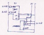
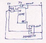
I send you drawings of my circuits - avoiding LED-connections and AXE=027-connections. I had a lot of trouble reducing them to a size this pgm will accept, but I hope you can read them.
The pgms look as follows:

Code:
	  #Picaxe 14m2
	  #Terminal 4800


 main: 	
 		high B.3
		pause 500                                    ;flash
		low B.3
		sertxd (cr,lf,"AA")
		rfout B.5,($1,$1,$1,$1,$1,$1,$1,$1)           
		sertxd (cr,lf,"BB")
		high B.3
		pause 500                                    ;flash
		low B.3
Code:
 #PICAXE 28X2
#Terminal 9600


symbol data1 = b1
symbol data2 = b2
symbol data3 = b3
symbol data4 = b4
symbol data5 = b5
symbol data6 = b6
symbol data7 = b7
symbol data8 = b8


MAIN: sertxd (cr,lf,"AA")
	high A.1	
	pause 5000    ;flash
	low A.1
	rfin C.4,data1,data2,data3,data4,data5,data6,data7,data8
	high A.1	
	pause 5000    ;flash
	low A.1
	sertxd (cr,lf,"Received: ",#data1,#data2,#data3,#data4,#data5,#data6,#data7,#data8)
torben
 

Attachments

friis

Senior Member
Hi hippy,
There is an error in the drawing of the RX-module. The 4.6 kOhm resistor is a pull-up resistor and actually connected to +5V.
torben
 

hippy

Technical Support
Staff member
Fisrt thing I would do is simplify the code ...

Code:
#Picaxe 14m2
Do	
  high B.3
  pause 500
  low B.3
  rfout B.5,(1,2,3,4,5,6,7,8)           
  pause 2000
Loop
Code:
#PICAXE 28X2
#Terminal 9600
Do
  rfin C.4,b1,b2,b3,b4,b5,b6,b7,b8
  sertxd (cr,lf,"Received: ",#b1,#b2,#b3,#b4,#b5,#b6,#b7,#b8)
Loop
Then report on what results you are seeing.
 

friis

Senior Member
Hi hippy,
There is an error in the drawing of the RX module. The 4.6 kOhm resistor is actually a pull-up resistor connected to +5V.
torben
 

friis

Senior Member
Hi hippy,

Here is the result of the test (serial terminal). The distance in time between the lines varies between - say - 5 sec. and more tha 120 sec. I cant see any system in it, but there are not 8 char. per line.


Received: 95423219765170173211
Received: 21612791667817160237
Received: 1388019549147169170128
Received: 245119342081167988171
Received: 19813890136116586648
Received: 21878016961569310
Received: 13842021741326018458
Received: 2072159393113216172153
Received: 2411141651661142463794
Received: 17119376166140246221182
Received: 1824690123108348659
Received: 35239159421734110243
Received: 1221624321641
Received: 2481081712543467168174
Received: 2492318123789161166
Received: 841102181781432318267
Received: 29852338290233126149
Received: 2024713813816719311146
Received: 8439402621425210665
Received: 12416243216419
Received: 2012126180172186175186
Received: 21212415647241637114
Received: 2072234313420160176117
Received: 16037221852379016785
Received: 2248717017724855223170
Received: 2273351104164174175130

torben
 

friis

Senior Member
Hi hippy,
This is what I got with the sender disabled and spaces between b1, b2,........:

Received: 189 251 246 193 64 80 85 241
Received: 14 90 163 105 46 151 202 110
Received: 226 135 253 85 209 77 238 237

So it is noise it is getting and the sending is the problem.
torben
 

hippy

Technical Support
Staff member
Not quite sure what's going on. There are a couple which jump out as interesting ...

Received: 1221624321641
Received: 12416243216419

It might be worth adding spaces between the #bx in the SERTXD to show exactly what is being received in each byte or print the numbers out as binary. It does seem to be rather random but there may be some pattern to it.

I am not familiar with the modules you are using. It may help to post photos of your setup, describe the hardware in detail or post photos of that.
 

friis

Senior Member
Hi hippy,
I have tried to change rfout from B.5 to B.4, I have again changed the TX and RX modules, but no change. I have tried to remove the pull-down resistor from the RX module, and the noise received disappears. I wonder what /CS for the enable pin means.
torben
 

friis

Senior Member
Hi hippy,
I have added spaces between the #bx and that shows that 8 bytes are received. But the removal of the pull-down resistor shows that the noise is generated in the RX module. I will try and take pictures, but they are going to be rather complicated due to the number of connections.
torben
 
Last edited:

hippy

Technical Support
Staff member
/CS would normally an "Active Low Chip Select". Though not fully described in the rather limited datasheet it would normally indicate the module will only function as desired when /CS is taken low. When high the module will be disabled, possibly put into a low-current consuming sleep mode.

Removing the /CS pull-down would likely let it float high which stops data being passed from the module to the PICAXE so RFIN would not receive data, and consequently the program waits forever in RFIN.

It might be worth trying with /CS direct to 0V rather than through a 10K but I would not have expected that to be the issue.

Unfortunately diagnosing RF radio problems is a difficult business and often a lengthy and frustrating one. You could perhaps try the alternative SEROUT and SERIN transmission technique for dumb RF modules rather than using RFOUT and RFIN to see if that fares any better and that may allow an easier analysis of the problem.

Do you have an oscilloscope or logic analyser which would allow you to look at the output from the RF receiver ?
 
Top