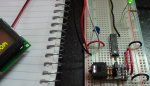
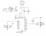
I breadboarded the attached circuit and hooked it up to an AXE132 which I mated to a 16x2 HD44780 Character LCD Display Module that I got from e-Bay.
I downloaded the attached program which has been tested and runs perfectly on the simulator.
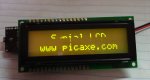
Yet when I connect the power, the display reads:
“Serial LCD”
“www.picaxe.com”
It seems to me that the AXE 132 is not receiving the data stream from the 18M2. How can I test this?
In addition, as seen from the photo, the lower half of Line 1 on the LCD is cut off. Is this a sign of a defective LCD or am I missing something obvious.
Thanks for your help.
I downloaded the attached program which has been tested and runs perfectly on the simulator.
Code:
' ************** TemperatureSensorSerial.bas **************
'This program runs on a PICAXE 18-M2 at 4MHz which reads the temperature from a
' DS18B20 temperature sensor & sends it to an HD44780 compatible 16x2 serial LCD display.
'
' Developed by Albert Zalner February 6, 2015.
' *** Constants ***
symbol LCD = C.6 ' Assign LCD to port C.6
' *** Variables ***
symbol Temp = b20 ' calculation variable
symbol Temperature12 = w11 ' Temperature word using b22 & b23
symbol TempC_100 = w12 ' Temperature value in C * 100 (uses b24 & b25)
symbol Tempsign = bit0 ' The sign of the temperature reading
symbol Whole = b2 'The whole temperature reading
symbol Fract = b3 'The fraction temperature reading
' *** Directives ***
#com 1 ' specify download port
#picaxe 18M2 ' specify processor
#no_data ' save time downloading
#terminal off ' disable terminal window
' *** Initialize the LCD ***
' *** Control commands are all prefixed by the number 254 ***
iniLCD:
serout LCD,N2400, (254,1) 'Clear Display
pause 800 ' pause 800 mS for LCD initialization
serout LCD,N2400, (254,128) 'Move to Line 1, Position 1
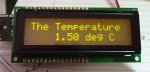
serout LCD,N2400, ("The Temperature") 'Output Text
main:
serout LCD,N2400, (254,196) 'Move to line 2, position 4
call ReadTemp12Sensor 'Read the temperature
goto main 'loop to beginning
ReadTemp12Sensor:
'**************************************************************
'** Read DS18B20 & display temperature in 12 bit resolution **
'**************************************************************
ReadTemp12 B.3, Temperature12 'Read the DS18B20 temp sensor
Pause 800 'pause 800 ms per DS18B20 spec
'TempSign = Temperature12 / 256 /128 'Isolate the MSB bit
TempSign = Temperature12 / $8000 'Isolate the MSB bit
If TempSign = 0 then Positive 'Test for negative
Temperature12 = Temperature12 ^ $ffff + 1 'Take 2's complement
Positive:
TempC_100 = Temperature12 * 6 'TC = value = 0.0625, TC*100 = 6.25
Temperature12 = Temperature12 * 25 / 100 'the rest of the value
TempC_100 = TempC_100 + Temperature12 'the temperature value * 100 in C
Whole = TempC_100 / 100 'separate the whole degrees
Fract = TempC_100 % 100 'separate the fractional degrees
If TempSign > 0 then 'temp is negative
Serout LCD,N2400,("-") 'send negative symbol
end if
Serout LCD,N2400,(#Whole) 'Send temp to LCD as a whole number
Serout LCD,N2400,(".") 'send decimal point
'*** To ensure the fraction is double digits ***
Temp = Fract / 10 'Calc the first digit of fract
Serout LCD,N2400,(#Temp) 'send first decimal digit to LCD
Temp = Fract % 10 'Calc the second digit of fract
Serout LCD,N2400,(#Temp) 'send second decimal digit to LCD
Serout LCD,N2400,(%11010010) 'send degree character
Serout LCD,N2400,("C") 'send letter ?C?
Return“Serial LCD”
“www.picaxe.com”
It seems to me that the AXE 132 is not receiving the data stream from the 18M2. How can I test this?
In addition, as seen from the photo, the lower half of Line 1 on the LCD is cut off. Is this a sign of a defective LCD or am I missing something obvious.
Thanks for your help.