Sensing movement in camera video signal

ZOR

Senior Member
I am trying to find circuitry for a video amplifier where a mask can be set over an area of the picture and any motion can be used to trigger alarms. It would be great if that movement change could determine if movements were of an object going left or right.

I came accross a very basic almost no good article using a PIC, and that's as far as I've got. Anybody gone down this road?

http://mondo-technology.com/viddet.html
 

hippy

Technical Support
Staff member
I would guess that is using the trick of taking the average video level of a frame and simply detecting if it changes much, doing that averaging by splitting the image into 8x8 sub-images.

It is possible to use a PICAXE to tell if video is present or not, the overall image is dark or light, and even possible to detect changes, but likely only as whole image. Video signals are really too fast for a PICAXE to process on the fly but would love to be proved wrong, and another page does describe some clever tricks where the image can be scanned more slowly -

http://mondo-technology.com/vax.html

You would probably be better off with a cheap single-board computer which has video processing built in.
 

ZOR

Senior Member
Thanks hippy, I will look around a bit more for any articles. Single board computer, another good idea, thanks
 

MFB

Senior Member
Could it be as simple as averaging a composite video signal and monitoring the relatively slow changes with an ADC input? Worth looking for examples of analogue averaging circuits, adding it to the output of a video camera and using a DVM to monitor the voltage level of change when viewing different images. If changes are detectable, then write some code to replace the DVM and respond to as required.
 

rossko57

Senior Member
Averaging business goes a bit wrong when the light suddenly changes; cloud passing (even indoors), artificial lights on/off, reflections or shadows from outside the area of interest. Depends on the application.

Edit : you can get secondhand commercial grade fixed cameras on eBay for twenty quid which incorporate their own motion detection and output an alarm signal on a pair of dry contacts. Look for brand names and check the features for any given model. Beware some require a 24VAC supply, but many are dual 24VAC/12VDC or mains.
No challenge, but it works. I got a box of eight assorted 4-8 yeare old wired cameras for twenty quid last week, four of them have this feature, although I have no use for it.
 

AllyCat

Senior Member
Hi,

.... a mask can be set over an area of the picture and any motion can be used to trigger alarms. It would be great if that movement change could determine if movements were of an object going left or right....
That is difficult to do with a microcontroller running compiled (even assembler) code, very difficult with a PICaxe. Yes, I have done it (with a more powerful controller, using assembler) and it needed quite a lot of additional dedicated hardware.

What the PICaxe might be able to do is define a "window" (box) on the picture which opens a gate to average the brightness inside the box. Then measure the average brightness (with an ADC) which might indicate (if different from a previous measurement) if a bright or dark object has entered or left the box, but it could NOT detect movement within the box, and certainly not the direction of movement.

Assuming you're considering standard "625 line" CVBS (monochrome) or RGBS (colour) signals, a single PICaxe instruction takes about as long to execute as a complete scan line, so no processing can be done directly along the horizontal axis. What the PIcaxe program might do is wait for vertical sync pulse, then pauseus until the window starts and pulseout until it ends. That "horizontal bar" output signal would need to be ANDed with a "vertical bar" to create the window gate signal:

A PICaxe PWM output signal could define a vertical bar, but the oscillator will need to create exactly 15.625 kHz (64us cycle) necessitating a crystal oscillator (i.e. likely a X2 chip), then using an analogue/software phase-locked-loop to position the vertical bar relative to the line sync pulses. A second, similar PWM oscillator might alternatively create the horizontal bar which could free up the PICaxe for other tasks.

To get sufficiently large measurement differences, you probably wouldn't want to compare adjacent frames but perhaps 5 or 10 apart. So after measuring the average brightness of the "reference" window, you might measure the adjacent North, South, East and West cells in subsequent frames. This possibly might allow the program to (sometimes) infer the direction of movement across the edges of the main window.

Cheers, Alan.
 

ZOR

Senior Member
Many thanks everyone for useful suggestions. What I cannot get my head round is how to define a "window" (box) on the picture and sense change. Looks an attractive direction to take but maybe very complicated to do?
 

AllyCat

Senior Member
Hi,

IMHO it just needs a good understanding of the TV scanning process. Any point on the picture (screen) can be determined in terms of its time delay after the frame sync pulse (at the top of the screen) and line sync pulse (at the left-hand side).

For example a 1ms pulse, 10ms after every frame sync wil define a horizontal bar about half-way down the screen. A second piulse 5us wide and 30 us after every line sync pulse will define a vertical bar. AND gate those pulses together to define a rectangle (where the bars cross) which could activate (enable) an analogue "bilateral switch" (eg. HC4016) to couple the video signal onto a capacitor (to accumulate/store an average voltage).

The most difficult part is likely to be the line (vertical bar) timing. Perhaps create a ramp (sawtooth) signal from the line syncs, slice it at an adjustable level using a comparator (to create a time delay) and perhaps trigger/clear the SR Latch to generate a pulse.

But as said above, there's no guarantee that simply comparing average values of the brighteness within a complete cell (box) will give very satisfactory indication of movement.

Cheerrs, Alan.
 

ZOR

Senior Member
Many thanks Alan. I am wondering if a low tech solution in my head might work. 2 cheap cameras, cardboard in front with windows cut out, one to left of image the other to right. I know from experience what you say about cameras auto light level changes causing a complete change in output, so maybe I could compare both outputs, i.e both flash ignore, single change then somethings moving in the respective window. I am trying to think this as my knowledge on frame sync pulses etc etc is zilch.
 

grim_reaper

Senior Member
ZOR, if you're considering going down the low-tech route of using cardboard, may I suggest a different direction!?
There's plenty of PC software available for monitoring video input and setting alarms; would it be worth considering a server to monitor your camera? I realise Hippy suggested the single board computer for video processing, but with a server running an OS you have a lot more complex software options available, and if you're trying to get the result into an 'AXE, output from the PC is also fairly easy.
 

nekomatic

Member
Wow, that looks fun! I wish I could think of an application right now so I could order one for work ;)

I'm sure a Raspberry Pi with camera module would be one of the most cost effective ways of doing this. I can't tell you exactly how to go about it but I'm sure you'd be able to get help from the Pi forums and so on, as there are definitely lots of other people using Pis for that sort of thing.
 

ZOR

Senior Member
Thanks, I'll start reviewing the options contributed, all very helpful. I was trying to keep things within a main camera system providing motion tracking control. I looked at PIR's but not very reliable, got lots of false triggers. Will look around at video amps and possibly Rasberry Pi. Thanks again all
 

ZOR

Senior Member
Jim, good to hear from you. I missed Pixy during adding posting, what a clever device? Like the coloured object following, could follow my cat to see where it goes all day.

"I/0 to the Picaxe and vidéo motion détection" Can you enlarge on this a little please so I have something to start with, thanks

Rasberry Pi looks a method, only concern is a new programing language, but as you say the Pi forum might be a good bet.
 

BESQUEUT

Senior Member
Jim, good to hear from you. I missed Pixy during adding posting, what a clever device? Like the coloured object following, could follow my cat to see where it goes all day.
"I/0 to the Picaxe and vidéo motion détection" Can you enlarge on this a little please so I have something to start with, thanks
Rasberry Pi looks a method, only concern is a new programing language, but as you say the Pi forum might be a good bet.
CmuCam is very good to detect coloured balls... but a cat...
You can dowload DS-2120 User Manual :
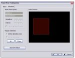
Page 76 : There are 2 sources of events: Camera (video image) and Digital Input. You can assign multiple events by following the instructions
below.

Page 78 :General Motion
Detect any movement in the defined detection zone.
Alarm Event Option:
• Sensitivity: Click and move the slider control to the right to increase sensitivity so that a relatively small movement will
trigger the alarm. Move the bar to the left to reduce the sensitivity of movement detection. Set up an appropriate Sensitivity
value will reduce the chance of false alarm. For example, you can lower the Sensitivity to avoid the alarm being triggered
by a swinging tree in the breeze.
• Interval: Click and move the slider control to the right to increase interval time so that the alarm will only be triggered when
the movement lasts longer. Move to the left to reduce the interval time.
Region Definition:
• Define detection zone: To detect General Motion, you have to define a detection zone. Left-click and drag the mouse to
draw a detection zone. You may define more than one zone on the screen by repeating the same process. You can also
click on the All button to select the entire detection zone.
Start Simulation: Click the Start Simulation button and test the function on the preview screen.
motion.jpg
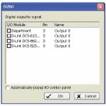
DI/DO
Use to trigger Digital Input/Output devices that are connected to the camera(s), such as alarm lights and sirens.
DiDo.jpg
You can use DI/Do to collect events from Picaxe or to set an interrupt in case off movement detected by Camera.
 

tony_g

Senior Member
zor are your cameras going back to some form of dvr or purely just to monitor on an external screen?

if a dvr then most if not all do offer a user selectable masking area for movement detection, i use such a feature for one of my cameras to save the hdd space and kick in pre alarm record and higher frame rates for better captured footage (evidence when its something untoward lol)


tony
 

ZOR

Senior Member
Thanks Tony, yes my cameras go back to a dvr which has movement/alarms. I was trying to build something within the camera unit to follow an object. I could feed the alarm signal back to the camera to give it knowledge something was moving however would not be able to tell the camera to move left or right.

I have seen cameras on the market that track objects, but expensive. As I said earlier I gave up testing ideas using PIR's as I had so many false errors.

Still looking at Pixy, however I think it needs to be taught what colour to look for, difficult with a burglar.
 

tony_g

Senior Member
ah ok, i wasnt sure if you were just more after object detection in general within the current view but yes a worthwhile feature if it can be had without a huge price tag.
 

Buzby

Senior Member
I don't have a DVR, but I do have a software package on a PC, which has similar motion detection to a commercial DVR. It also has masking, and the ability to trigger a physical output ( mine is old, so it uses the parallel port. )

It may be possible on a more sophisticated device, like your DVR, to trigger different outputs ( or serial out ) when different masks are active. If this is the case then it would be easy to use a PICAXE to drive some servos to point the camera at the area currently triggering.

I would have a good read of your DVR documentation to see if there is a way of using it's intelligence, instead of ours ! :)
 

tmfkam

Senior Member
How about using an LM1881 sync separator? This will extract both field (along with odd/even field - giving frame) and line sync timing pulses which could be used to start a counter within the PicAxe to trigger the selection of 'an area of interest' within the video signal that the PicAxe could then compare to see if something had changed from the previous sample.

The TI datasheet (http://www.ti.com/lit/gpn/lm1881) shows an outline circuit for a line selector which could be used to feed the selected video line (or lines) to the PicAxe for comparison purposes or or other additional circuitry.

Using something like the LM1881 might off load some of the time critical processing giving the PicAxe more time to do the intended computation.

One other thought might be to use some additional infra-red sensitive devices on the camera mount and track simple infra-red movement with the PicAxe, using that tracking information to move the camera, at the same time moving the infra-red devices.
 

ZOR

Senior Member
Many thanks tmfkam, I think I will give that idea a try, just going to order on Ebay, very cheap. I know nothing about frames/sync pulses etc but will stick my scope I bought from RevEd and not used yet and hope by seeing something might find my way further. Been looking at Rasberry Pi, and using TinyBasic being nearer to the basic language familier to me, but don't want to and get a long round the block solution.

The LM1881 (if I knew what I was doing) could be a cheap effective way to link with the Picaxe. Thanks again
 

tmfkam

Senior Member
Television and analogue video signals are something I am reasonably familiar with, if I let you have a little background information, it may help you see what my idea was and whether it will be suitable for your application.

A television picture is made up of a number of lines, each line is scanned starting with line one at the top left corner of the screen, line one being completed at the top right of the screen. Line three starts not quite directly under line one, again at the (nearly top) left and finishes on the right. Each successive (odd numbered) line is positioned underneath the previous one until the bottom right corner of the screen is reached. To do this requires some timing 'markers' so that the viewing screen is synchronised with the transmitting screen to ensure that the picture is correctly displayed. With no timing the picture would be nothing but a jumbled mess.

In the UK the picture is made up of 625 lines, this is broadcast in two fields of 312.5 lines, two fields making one frame. The 312.5 lines of one field are positioned with a slight [one horizontal line] vertical offset so that they are interleaved with one another, they do not overwrite the other field [interlaced]. The fields are transmitted in what is considered to be odd and even numbered fields, the odd field having line numbers 1, 3, 5, 7... then the even field with lines 2, 4, 6, 8...

A line is transmitted every 64uS, a field every 20mS, and a complete frame every 40mS.

The LM1881 takes a composite video signal and decodes it into the timing signals, the field sync pulse indicating the start of the field (600uS wide), the line sync pulse indicating the start of the line (5uS wide) and the frame sync indicator denoting whether the next field is odd or even (a modified field sync pulse).

If you wanted to look at an object that was in the dead centre of the screen, you would need to start a counter at the end of the field sync pulse, count 156 (half of 312.5) line sync pulses, pause for 32uS (half of the 64uS line length) and then start looking. For near to the top left corner, count 5 line sync pulses, pause for 10uS then start looking. For something that was nearly in the bottom corner, you'd have to count 300 line sync pulses, pause for 50uS and then start looking. Unless your object was one pixel wide, by one pixel high, this wouldn't be terribly practical, but hopefully it gives you somewhere to start your thinking from. Due to various 'housekeeping' features provided by the broadcast signal, these timings are not going to be absolutely accurate, but they should be close enough to get you on your way.

I have only considered analogue signals here, but I would be surprised if your video cameras do not have analogue outputs. If they are IP cameras, or network connected cameras they could be fully digital, if that is the case this theory (and the LM1881) will be wasted. The interlacing is not likely to require consideration either, unless you really are trying to track something that would only be visible on one single line, and not on any other. Also this does not consider colour, unless you really need to track very specific colours I'd ignore it. If you do need to track specific colours you'd need to do some decoding of the PAL colour signal first, that would give you the red, green and blue colour signals from which you would need to determine how to combine and filter these colours to eliminate unwanted colours yet leave the wanted ones. Not for the faint of heart!

The line selector circuit that TI showed in the datasheet for the LM1881 would allow either one line, or a number of lines to be passed through for further processing, this would give a thin horizontal 'slit' of complete lines, if you were interested in something that was to the right hand side of this 'slit' you would have to still wait for up to 50uS after the line sync pulse before asking the PicAxe to look for the changes you require.

The Wikipedia page on PAL has some oscillograms of video signals which neatly illustrate the picture information as it is transmitted. http://en.wikipedia.org/wiki/PAL

There is an article on the NI website which again shows some of the theory of a video signal. http://www.ni.com/white-paper/4750/en/

Good luck!
 

ZOR

Senior Member
Many thanks tmfkam for taking the time to post what you did. I am hoping this together with whatever I see at the output on a scope will start making sense.

My camera is a CCD (Sony) Analogue CCTV camera.

So thinking out loud, the camera output goes into the input of the LM1881. The output of the LM1881 goes into the Picaxe.
I need to get my head round on the Picaxe, where does / how does counting come in, and what am I looking for out of the Picaxe? PWM pulse?

Sorry to be totally thick but in the complete dark.
 
Top