WTV020-SD-20SS
A few days ago I bought one of these cheap modules on ebay with the ambition of adding voices to a project, taking advice from this forum I managed to buy an SD card that was compatible and soon got it working in "Key Mode" but of course I wanted a picaxe to control it and that was when I ran into difficulties.
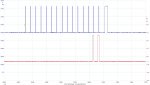
I am sure the code is right and have checked the output on my scope (see photo) but after several days I've had no joy. Looking round on internet I found some suppliers say that it must be programmed into serial mode at manufacture, does anyone know if this is correct as the add did not suggest this.
I have also included my latest code if anyone can see anything wrong there I would be very grateful for any help or suggestions as I have spent many many hours trying to solve the problem and got nowhere. (Hope I've done the attachment and code right") )
)
A few days ago I bought one of these cheap modules on ebay with the ambition of adding voices to a project, taking advice from this forum I managed to buy an SD card that was compatible and soon got it working in "Key Mode" but of course I wanted a picaxe to control it and that was when I ran into difficulties.
I am sure the code is right and have checked the output on my scope (see photo) but after several days I've had no joy. Looking round on internet I found some suppliers say that it must be programmed into serial mode at manufacture, does anyone know if this is correct as the add did not suggest this.
I have also included my latest code if anyone can see anything wrong there I would be very grateful for any help or suggestions as I have spent many many hours trying to solve the problem and got nowhere. (Hope I've done the attachment and code right
)
Code:
#picaxe 18m2

Symbol mask	= bit0	        	; Mask word for the shiftout proceedure
Symbol index	= b1				; Bit counter for shifting data
Symbol track	= w1				; Pointer to the required track file
Symbol dat	= w2			        ; Data to send to module is a word(16-bit) value
Symbol msb	= $8000		        ; Mask for the most Significant Bit = bit 16
Symbol sdat	= b.4		        ; Serial data output is on pinb.3
Symbol clk		= b.5			; Serial clock output is on pinb.2
Symbol busy	= pin1		        ; Busy line back from module
Symbol rset	= b.6			; Reset line for WVT020 device

Init:
	Low sdat						; Data line Low
	High clk						; Set clock to high	on WTV020 device
	High rset						; Set reset line high on WTV020 device
	Pause 2000
Main:
	track = 6
	Low rset						; Reset the device
	Pause 5						; For 5ms reset pulse
	High rset						; then high again
	Pause 300						; Delay 300ms
	dat = track					; Load track number into dat
	Low clk						; Pull clock-line low to start
	Pause 3						; Start-bit time >= 2msec to indicate a start of command

	For index = 1 To 16				; loop for each of 16 bits of filename/number
  		mask = dat And msb / msb 	; mask out the most sig. bit to ascertain if next bit is 1 or 0
		Low sdat
		If mask = 0 Then Skip		; check if current data bit is "0" skip if it is a zero
		High sdat					; set data line high only if the data bit is a "1"
Skip:
		If index = 16 Then Skip16th	; Skip here as 16th bit is clocked out at the end
		Pulsout clk, 20				; Create 200usec clock pulse for the current data bit
  		dat = dat * 2				; shift data one bit left

Skip16th:
Next index					; Get next bit till all 16 bits of data presented to module
		High clk			; Pull clock-line high which also clocks out the 16th data bit
		Pause 3			; End-bit minimum time >= 2msec for STOP indication
		Low clk
		Low sdat
		End