AXE 021 08 proto board with extra LEDs

WHITEKNUCKLES

New Member
The numbers in this subroutine give about 90 cycles per minute on pin0 and pin1 while pin2 Flickers continuously.
It uses 37 bytes so on this SM 08M there is the possibility of having 5 such subroutines with altered numbers and possibly room for a random routine to select them.
Note the 'return' is commented out and a 'goto aa' added.

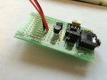
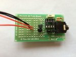
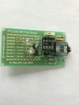
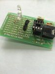
It has been copied and pasted into the Programming Editor, downloaded into a 08 Proto Board and is running continuously.
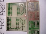
If FETs were mounted in the first/second row of holes the third row could have standard 0.1 inch header pins and the rest of the Proto Board cut off to save almost an inch in length.

So this might all you need. Easy soldering and easy download but change the pins so that you would not be bothered fiddling with the jumper on pin0.
Using an 08M2 would mean that such a variety of routines could make a contiguous program taking so much time to run that it is doubtful if anyone could recognise the repetition.

Dave

https://www.fairchildsemi.com/datasheets/2N/2N7000.pdf


aa:
for b4=1 to 8 ' ...........Number of times sequence is repeated
high 0
low 1
for b6 = 1 to 8 ' ........Timing of Flash instead of a pause
toggle 2
pause 44'..................Time for Flicker to be visible
next b6
low 0 '....................Alternate colour of Flash
high 1
for b6 = 1 to 4
toggle 2
pause 44
next b6
next b4
'return
goto aa
 
Last edited:

jensmith25

Senior Member
Hi Dave, firstly, thank you very much for your help. It is very much appreciated. Please excuse my lack of knowledge but can you help me understand a couple of things?

Note the 'return' is commented out and a 'goto aa' added.
Why is this?


So this might all you need. Easy soldering and easy download but change the pins so that you would not be bothered fiddling with the jumper on pin0.
That would be ideal - to use the 08 Proto board as it's easier for me to adapt to other projects. I don't know how you would change the pins to avoid the jumper on pin0?

I have found the FET on my electronics suppliers website so that's no problem to buy but just so I understand, why this one rather than a different type? Is the FET better than a basic transistor?

aa:
for b4=1 to 8 ' ...........Number of times sequence is repeated
high 0
low 1
for b6 = 1 to 8 ' ........Timing of Flash instead of a pause
toggle 2
pause 44'..................Time for Flicker to be visible
next b6
low 0 '....................Alternate colour of Flash
high 1
for b6 = 1 to 4
toggle 2
pause 44
next b6
next b4
'return
goto aa
Thanks very much for the code sample. I'll try that out asap. One thing.... what are b6 and b4? Is this for the 08M? My 08M2 chip the pins are C.0, C.1 etc or is it symbols for the LEDs?
 

WHITEKNUCKLES

New Member
Top of this page click Manuals, click 2, left column search for (heading) or (pages)
[Moray House has much to answer for.]

Post # 40
Shows the label aa: (label) (6) for the subroutine listed below it.
Subroutines are 'called' by the main program with (gosub) instruction (71)
After execution the subroutine will (return) (195)

Post # 41
The (') before the 'return' instruction converts it to a comment which is ignored by the Editor.
The (goto) (72) converts the subroutine to a stand-alone program that can be run continuously on its own by being sent back to aa:.

Pin0 (GPIO0) is Microchip nomenclature for input/output pin0 and used by Picaxe 08xx for output to the PC during download
The jumper makes pin0 into a useful output pin but constantly swapping the jumper before and after the download can be tedious if like me programming is : try it, fix it, try it.......
For three outputs use pins 1,2,4 but only if you don't like swapping the jumper.

Not best practice but some FETs can be used without the attendant base resistor used with a bjt.
The 2N7000 is old, near bullet-proof and cheap.

(Variables) (11)
Understanding the variables is essential for programming all Picaxe microcontrollers so read this and try to understand the B0 or b0, B1 or b1, b2 etc.

Variables are like glass jars with their name on the outside and something stored inside that can be:
Examined :
if b2 = 0 then goto........
Changed:
let b3 = 4
Emptied:
b6 = 0

Copy the program into the Picaxe Editor select 08M2, press F4 for a syntax check then click simulate, click run, or else!

Dave

10 for £1.69
http://www.ebay.co.uk/itm/10PCS-or-1x-2N7000-TO-92-Transistor-UK218-/291250980389?pt=LH_DefaultDomain_3&var=&hash=item43cfe94625
 

jensmith25

Senior Member
Hi Dave,

Thanks for that. I think I follow it all.

I'm on a mac so I don't get the easy simulate option with the Axepad but I have an old windows laptop I can try it on tomorrow.
 

jensmith25

Senior Member
The 2n7000 FET's arrived today so I did a test layout on the 08 proto board and would like to check I'm on the right track before soldering!

Based on the datasheet I have put the "Source" leg to the picaxe pins, "Gnd" I've bent the middle legs to sit into the Gnd holes in the board and the "Drain" leg goes to the LED in the third line of holes. The red and black wires represent two LEDs.
This is just a basic test to make sure I'm doing it right.

08M_protoboard_FET2.jpg

08M_protoboard_FET1.jpg

I wasn't sure how to connect the GND leg from picaxe pin 3 as the leg is too short. Is it best to solder on a wire to the FET leg and wire it to gnd that way? Is that actually best practice in general or is bending them ok?

Thanks very much.
 
Last edited:

The bear

Senior Member
Hi Jen,
Bending them is fine IMO.
I do like following your projects, makes real good reading.
Good questions, I'm learning from the answers too.
Regards, Bear..
 

nekomatic

Member
I'm not sure that you have the MOSFETs and LEDs connected correctly there. For an N-channel MOSFET like the 2N7000 you are going to want to switch the low side of your load, and you'll connect it as follows:

G on a MOSFET stands for 'gate' and that should be connected to the PICAXE output - I expect it's OK to connect it directly for a small device like the 2N7000 but best practice would be to connect it via a low value resistor, say 100 ohms. (The gate has a certain capacitance so this resistor limits the current that flows when the PICAXE output changes state - once the gate capacitance is charged hardly any current will flow.)

S stands for 'source' and connects to ground. (If that sounds illogical remember it's the source of electrons, which are negatively charged.)

D stands for 'drain' and connects to the negative lead (cathode) of the LED.

Connect the positive lead of the LED (anode) to the positive supply voltage, via a series resistor to limit the current to the value that gives your chosen brightness. If it's more convenient you can wire positive supply - LED anode and LED cathode - resistor - MOSFET drain instead.

When the gate is at the same voltage as the source (PICAXE output low), the MOSFET is 'off' and doesn't allow current to flow into its drain. When the gate is a few volts higher than the source (PICAXE output high), the MOSFET turns on and the drain-to-source resistance becomes low, allowing current to flow through your LED, into the drain and to ground.
 

jensmith25

Senior Member
Ok, tried again with a practise layout. Have I got it right this time? Hopefully the pictures are clear enough and I haven't made another silly mistake like failing to read the 2n7000 diagram correctly.

08_FET1.jpg

08_FET2.jpg

I think, for it to work, I would need to put the resistors on the wire lead to the cathode of the LEDs as neomatics alternative suggestion as I need 2 LEDs off one pin and 2 LEDs off the other.

It seems quite hard to get the 2n7000's on the board in the space available.
 

WHITEKNUCKLES

New Member
Jennifer,

If you intend bending legs on components I would suggest that you grip the leg close to the body of the part with very narrow nosed pliers and do the bending as tight as you like below the pliers.
You will then be straining the leg without stressing the component.
My fets are SM so ordered some through hole 2N7000 to try to help if needed.
Dave
 

jensmith25

Senior Member
Thanks. I often bend legs on LEDs so I use pliers for that. I bent them with pliers in this case too.

I've got a programme that works now on a 14M project board, so just need to get the 08 PCB sorted.
 

jensmith25

Senior Member
My customer has asked this morning if the red eyes can fade and brighten requiring them to be run off the 08M2 chip rather than off the battery.

I'm now wondering if I'm better off going back to the darlington driver option so that I can more easily fit everything on the PCB? It's going to be quite difficult to fit 4 of the 2n7000's on the board I think?
 

premelec

Senior Member
Note that PWMOUT gives very nice fade up and down function [14M2s have 4 PWMOUT pins 08M2 only one] - I haven't tracked what you use the 2N7000s for...
 

The bear

Senior Member
Hi Jen,
I saw on the forum, a while back, someone had used a tune, Rudolf, to make leds flicker.
C.2 is the tune output. Drat, its the PWM output as well.

Regards, Bear..
 

jensmith25

Senior Member
Note that PWMOUT gives very nice fade up and down function [14M2s have 4 PWMOUT pins 08M2 only one] - I haven't tracked what you use the 2N7000s for...
I've got the PWMOUT working though it needs to be slower. What's the best way of doing that? Note the LED isn't meant to go off, just dim. I want the eyes to always be lit.

Code:
main:
for b1=25 to 255
pwmout B.2,255,b1
next
for b1=255 to 25 step -1
pwmout B.2,255,b1
next
goto main
The 2n7000's were to enable me to use 2 LEDs on each 08M2 pin. Now my customer wants 7 LEDs on the pins so I thought perhaps the Darlington driver ULN2003 might be a neater end result as previously discussed earlier in this thread. (page3 maybe)
 

jensmith25

Senior Member
Thanks Bear - that's pretty good idea. I've managed to get the random flash and flicker so just need to get it all on the PCB now.

I'll post everything when it's done.
 

premelec

Senior Member
You can bias your LEDs on minimal all the times with a resistor and then _add_ PWM to that to modulate them to higher level - or you can idle PWMOUT pretty low but not off... whatever works...As far as slower just put in a delay for PWMOUT duty changes - I have some running at very slow change rates [think cloud passing...]... It's a trial and error process to what suits you - or you can get fancy and put in an LDR which changes the PWM change speeds with ambient light [slow in the dark and faster in lighted environment] - that might take a 14M2 - a bit more expensive and a lot more versatile.
 

WHITEKNUCKLES

New Member
Jennifer,

Saw your preference for the 14M2 and wondered if you could drive your 7 LEDs from individual pins and get the brightness that you need?
If this is so then you might care to send an SAE for one or both basic 14pin boards for your project, or note my mistakes, I don't have a working 14M2.

The Picaxe could be programmed on your existing board. There are holes for 0.1 inch or 0.2 inch capacitors and what I hope is a download resistor.
The images are done by toner transfer filled in with GreenTRF and touched in with pen before etching, need cleaned, soldered and drilled if wanted.

Later I saw Eclectic's good links but these boards might be smaller but they certainly are cheaper.

Dave
 

Attachments

Last edited:

WHITEKNUCKLES

New Member
1 inch x 1.4 inch
The bottom resistor and it's pads could be sawn off leaving 7 outputs.
Putting the download resistor under the chip socket would save 1/10 inch but a bit of a bodge.
So 0.9 x 1.3 inch.

Definitely need to know if 7 single outputs would be acceptable.

Dave
 

premelec

Senior Member
I don't know if you've considered other construction methods... some with NO PCB... one called "dead bug" construction is laying the IC on it's back and soldering directly to it's legs - with various bits in thin air - eventually to be potted in plastic if you need to... it's more of an arts & crafts construction method... quite workable once you get the hang of it. Eventually you could use a SMD 14M2 on a tiny PCB. A fine point soldering iron is necessary... as well as some jeweler's pliers to make clever lead bends...
 

WHITEKNUCKLES

New Member
Premalec,
I had considered a dead bug glued to the top of the 08M2 but given resistance to using SM I considered it a non-starter here. A SM 14pin toner transfer board might be possible but much info needed.

Another Windows 8 download robbed me of my PCB files and I have recently started to remake those files and am experimenting with a heated roller for Toner Transfer with fair results hence my present willingness to make boards.

Eclectic's suggestion of using 2 off 08M2 is good but you say that you are not yet able to solder SM boards.

I have long felt that people shy away from SM only because they have not made a serious attempt at it and so I made the boards on the right of the photo in post # 63.
These boards are a half way house towards SM.
While using standard through the board components everything must be soldered on the top surface.
This is not an off the wall idea that I have suddenly thought up on the spur of the moment, I started a thread on 20.09.2007 and the photo there shows SM boards and half way house boards.
Both boards with DIP 8pin sockets have tracks with holes suitable for TH download resistors and capacitor but have been populated with SM components for ease and speed.
The new boards in post # 63 have no extra small sockets for download but do have a position for a SM led and resistor.

I have worked on boards with some TH components mounted SM but a recent repair was on the motor control and relay board on a Migatronic 160A welder where the entire board was all through hole mounted as SM.

So Jennifer if you fancy using two 08M2 Picaxe on this project or if anyone wants to try these boards or indeed a small SM board an SAE please.
Please note on the DIP boards there is a small via on an arc that must be drilled out if SM resistors and capacitor are to be used, I have a few R &C that I could send with a board intended for SM only.

Dave


http://www.picaxeforum.co.uk/showthread.php?7784-Autonomous-08-sideboard-for-development
 

premelec

Senior Member
Hi Dave, some years ago I made some SMD stuff - as you say quite possible - Main trouble was if you dropped a part you might never find it again. Also I used a loupe lens while soldering [70+ year old eye...]. I'm not sure why 2 08M2s would be better than one 14M2 [which would have 2x the PWMOUTs]. I've built many 08 projects and like the added features of 14M2s with not a lot of additional cost... I haven't followed all this thread so likely some of my suggestions are off.... I used to hand draw PCBs with marking pen ink - messy looking but looked ok - trick was to drill holes before using marking pen :) I'd appreciate a 14M2 or 20M2 SMD basic board ["breakout board"] perhaps with room for TO92 regulator and basic caps if you get inspired - I've mainly stayed away from 18pin as the power and programming pins are in different physical position than 08 14 20 pin units...
 

WHITEKNUCKLES

New Member
Greetings Eclectic,

Thank you for the info on the 08 SM headers and in post # 64 Jennifer mentions having one so I hope to hear her comments on your suggestion.
Perhaps not the smallest for 2 considering the header positioning?

Morning Young Permelec,

For me the advantage of 2 off 08M2 boards would be the ease of programming 2 separate tasks without interaction, or learning about Starts.
My 08 SM boards are 10 x 20mm and back to back 2 would be 7mm thick but I do have double sided fibreglass board only 0.42mm thick, no photoresist so Toner Transfer only, pity!

My loupe is 1. 1/2 inch but that is in front of my wife's spare +7 bifocals which are a wee bit stronger than my £ shop readers.
Via Dosbox I am still using Protel Autotrax which is a free download from Altium so send a circuit on the back of a fag packet or an Autotrax file and we could be in business on the 14pin at least.
It's Gerbers are out of date so DIY only, or in this case DIM. Please see photo in post # 63 and link in post # 67, SAE for your selection.

Dave, the Fox with no tail?

http://techdocs.altium.com/display/ALEG/Legacy+Downloads
http://sourceforge.net/projects/traxprint/
http://airborn.com.au/layout/autotrax.html
 

jensmith25

Senior Member
Thanks all for your input. I'm running to a bit of a deadline and want to keep things as simple as possible. I have a programme that works so that's ok. I don't really want to be chopping and changing and using a board I'm not familiar with at this stage because I just don't have time and I'd like to get it finished this next week.

I would prefer to have 2 LEDs on 1 pin because then they run the same code and they do need to be in sync. The only reason for preferring the 14m2 was because it is easy to use the darlington driver which would allow the extra current draw. I don't need the extra pins as such.
 
Top