AXE 021 08 proto board with extra LEDs

jensmith25

Senior Member
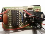
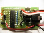
I have a project I'm working on that requires a small PCB - ideally the size of the 08 proto board AXE021 or smaller but that can run 6 LEDs.

Ideally I would use the 14m Project board AXE117 which is slightly too big or an 08 board with a darlington driver but that doesn't seem to be available.

As the 08m2 pins are ok up to 20mA is it ok to run two LEDs at 8-10mA off one pin or is this too risky?

This may be way off but as an alternative is it possible to use the AXE023 motor driver board which can take higher current?

Thanks for any advice,

Jennifer,
 

JimPerry

Senior Member
PICAXE outputs are rated to 20 mA each but be aware that most chips have a maximum of 95 mA total for the chip. So motor board is best bet. :cool:
 

jensmith25

Senior Member
They are superbright but at 3mm I'm not sure 5mA would be bright enough. I'd have to try it.

Thanks Jim - will the motor board work ok with LEDs or will it need any modifications to code or the board?
 

AllyCat

Senior Member
Hi,

IMHO the 20mA pin rating is largely a myth or "Chinese Whisper" (it seems to apply actually to the electrostatic "protection" diodes). From the "base" Microchip datasheet, the "Absolute Maximum" rating for an I/O pin is 25 mA, but that has the following note:

"Stresses above those listed under “Absolute Maximum Ratings” may cause permanent damage to the device. This is a stress rating only and functional operation of the device at those or any other conditions above those indicated in the operation listings of this specification is not implied. Exposure above maximum rating conditions for extended periods may affect device reliability."

For a "good" design it's necessary to look later in the datasheet for the typical (or the max/min) ratings of the I/O pin drivers. Those values depend on various factors such as the supply voltage and temperature, but the "guaranteed" figures (with a 5 volt rail and no more than 0.6 volts "lost" in the chip) are that a pin can pull DOWN 8 mA and pull UP 3.5 mA! In most cases those figures are unduly pessimistic, but IMHO it needs a true optimist to expect to get a pull UP of 15 or 20 mA. ;)

However, my answer to the original question may now surprise you: Provided that you use a separate current-limiting resistor for each LED and drive the pins "active low" (i.e. pulling current into the pin down to ground with the LEDs to the supply rail), there's a reasonable chance (but not a guarantee) that an 08M2 pin can light two LEDs at about 8 mA in each. Furthermore, 6 x 8 = 48 mA is within the "ground pin" rating of the PIC(axe) up to 85 degrees C. But not above 85 degrees C, which has an Absolute Max. rating of 30 - 35 mA.

Also, as "e" says, using "superbright" (or even hyperbright) LEDs can make an enormous difference. But do check the datasheet for their "viewing angle", some produce only a very "hot" spot.

Cheers, Alan.
 

jensmith25

Senior Member
Hi Alan,

But surely what you are saying, based on the actual specifications, that no standard chip 08m2 or larger can therefore power LEDs without a darlington driver but there's lots of PCBs out there for LEDs with no additional drivers that power them quite happily. Or am I misunderstanding?

In this application the viewing angle isn't important as they're for inside a model, hence the space limitations. Everything has to fit inside the body cavity.

I would use a separate resistor for each LED as I always use them anyway. I'm not sure I understand how to achieve the "active low" pins.
 

AllyCat

Senior Member
Hi Jen,

there's lots of PCBs out there for LEDs with no additional drivers that power them quite happily.
There's lots of badly designed boards out there. ;) But seriously, the manufacturers' "Worst case" data is intended as a "guarantee" that every device will work properly. If you're making (say) 1,000 or 10,000 PCBs a day, it's a problem if 1% (or even 0.1%) fail to work properly.

So, in practice a hobbyist can "push" the data limits a little, but how far? Perhaps x2, but x6 ? However, IMHO pushing 8 mA to 16 is better than trying to push 3.5 mA to 16. Also, in many cases you will fnd that the subjective brightness of a LED at say 5 mA is hardly any different to that at 10 mA.

To use "Active Low", you wire the anode of the LED(s) to the supply rail, cathode through a resistor to the PICaxe pin. Then you turn ON the LED(s) by writing a LOW (0) to the pin(s). Turn the LED(s) OFF with a HIGH or INPUT command to the port.pin.

Cheers, Alan.
 

rossko57

Senior Member
Have I missed something ... why not just have the two LEDs in series, to present only "one leds worth" current draw? (and adjust the resistor)
 

jensmith25

Senior Member
Have I missed something ... why not just have the two LEDs in series, to present only "one leds worth" current draw? (and adjust the resistor)
You need higher voltage to be able to do that. As the LEDs forward current is between 1.8-3.5v depending on type and colour you need at least 6v to run 2 LEDs. I don't have the space for the bigger battery in this instance and the standard chip power supply is 4.5v.
 

jensmith25

Senior Member
Thanks Alan. I will give it a try with the 08 proto board and see if they're bright enough at a lower mA rating too.
 

Goeytex

Senior Member
Have I missed something ... why not just have the two LEDs in series, to present only "one leds worth" current draw? (and adjust the resistor)
It 'might' work depending upon the forward voltage of the LEDs, value of the current limit resistor, and the voltage droop at the I/0 pin. As long as there is a limit resistor, it won't hurt to try, but my guess is that the voltage droop will prevent the LED's from having enough forward voltage.

EDIT: I tested with 2 "no name" 5mm Green LED's, and they lit up ok with 330 Ohm resistor. Did not measure the current.
 
Last edited:

jensmith25

Senior Member
Update:

I've had a play this morning on a breadboard both with a couple of flashing LEDs in series and the same in parallel. Because the LEDs need to be blue & red it doesn't work having them in series because, as suspected, there's not enough forward voltage to light them up at 4.5v. Two red ones will light but pretty dimly.

Obviously two in parallel will work but it's then down to brightness and mA rating for the PIC(axe). It looks as thought 8mA would be bright enough with 3mm LEDs so I'm going to try that with the 08M2 chip and see if it will work with the two LEDs and "active low" as Alan suggested.
 

Dartmoor

Member
The original post said "Ideally I would use the 14m Project board AXE117 which is slightly too big or an 08 board with a darlington driver but that doesn't seem to be available."
I have made several projects using the AXE021 Picaxe 08 Proto Board with a 14pin ULN2003A 7 x Darlington Array (available from the Picaxe Shop).
It means that one of the darlington drivers gets shorted out by a PCB track, but the 08M2 doesn't have 7 outputs anyway!
The ULN2803 (16pin) does not quite fit on the board.

I will take a photo later, but it does fit nicely!
 

jensmith25

Senior Member
The original post said "Ideally I would use the 14m Project board AXE117 which is slightly too big or an 08 board with a darlington driver but that doesn't seem to be available."
I have made several projects using the AXE021 Picaxe 08 Proto Board with a 14pin ULN2003A 7 x Darlington Array (available from the Picaxe Shop).
It means that one of the darlington drivers gets shorted out by a PCB track, but the 08M2 doesn't have 7 outputs anyway!
The ULN2803 (16pin) does not quite fit on the board.

I will take a photo later, but it does fit nicely!
Dartmoor - That would be fantastic if it works well as that would solve my problem nicely.
 

inglewoodpete

Senior Member
It means that one of the darlington drivers gets shorted out by a PCB track, but the 08M2 doesn't have 7 outputs anyway!
The ULN2803 (16pin) does not quite fit on the board.
Better to bend the unused output pin of the ULN2003A up so that it does not short out.
 

Teazle

New Member
I'm not sure what you are trying to do but if the Picaxe boards aren't quite right for what you need it may be worth looking a little further afield. I've used böards from RK Education which have been excellent. They still use picaxe devices and they have one for an 8pin that will drive 4 LEDs....you may be able to add a couple more LEDs but, if you are talking about connecting some in series, it may be that 4 super bright will do just as well.
 

jensmith25

Senior Member
Thanks Teazel. I have used RK Education boards but they are square and unsuitable for this application and it's not a case of overall brightness, the LEDs are going in different places so 6 is the minimum number.
 

Dartmoor

Member
Better to bend the unused output pin of the ULN2003A up so that it does not short out.
Here are photos of two different AXE021 boards with a darlington driver chip on board. There is space.
One has a ULN2803 with 4 legs bent up, the other has a ULN2003 with 2 legs shorted to 0v.
As discussed in earlier posts, this might be bad practice - but it works for a one off hobby project? I thought the bent legs/pins looked a bit amateur (but I guess that is what it is . . . )?
Phone Misc 026 - Copy (800x600).jpgQuad Bikes & Xmas 029 (800x600).jpg
 

jensmith25

Senior Member
Thanks Dartmoor, I appreciate that. Which bit is bad practice? Shorting the legs or bending them up?
It's not actually a hobby project in this case.
 

Dartmoor

Member
Thanks Dartmoor, I appreciate that. Which bit is bad practice? Shorting the legs or bending them up?
It's not actually a hobby project in this case.
Inglewoodpete suggests it is better to bend the legs up. I did that the first time and thought it looked like the bodge that it was.
Shorting the legs works for me, but that is contrary to Inglewoodpete's advice & he has a lot more experience.
I included a photo of both, and either will fit.
Should solve your problem?
 

jensmith25

Senior Member
Thanks Dartmoor. I appreciate the photos etc. Yes, that should solve my problem. The ULN2003A should be fine for my purposes.

Thanks very much.
 

Dartmoor

Member
I will need help on why for that one! :)
I am not an expert, but here is "IMHO":
It is because there is a volt drop across the darlington transistor pair.
In fact this applies to any semiconductor junction; FET, 'H' bridge etc & even a diode.
Could be about 1.2v drop in this case.
You said the darlington driver was your preferred choice in the first post, and you will get enough volts to drive an LED. Plus you can switch dozens of LED's!
Worth noting the limitations, but it should be ideal for what you want.
 

jensmith25

Senior Member
Thanks Dartmoor.

Yes, the voltage drop isn't an issue as long as it can light up the LEDs, so that's great. Thanks very much.
 

WHITEKNUCKLES

New Member
Greetings JenSmith,

I have sent you a Private Message regarding PCBs that I am making.

After searching I have found a 'proper' PCB measuring 13mm x 23mm, a gift from a friend on another forum using an 8pin Pic to drive R B G LEDs through FDV303N FETs direct from the micro pins.

I have hacked it to accept an SM 08M Picaxe with the program input pin5 (GPIO5) to ground via a resistor and 3 Fets on (GPIO pins 0, 1, 2 ). These FETS are good for 800mA so could take several LEDs in parallel.
There are pads for SM resistors in line with the output pads alongside a pad connected to +V (VDD) for power to the LEDs so that the FETs will sink current to ground with a low command.
Programming is done on 3 wisps of wire to be cut off later and given your program I could download it here before sending if you wish to send me your address.

Dave

http://www.hk-tree.org/downloads/FDV303N.pdf
 

jensmith25

Senior Member
Thanks Dave, I have replied.

In case Dave's PCB isn't suitable I need to just check a couple of things if I may. Sorry, I'm very much still trying to get past very noob stage. Before I damage any components....

1) I've been looking at the photos Dartmoor provided, my 14m project board and also the Manual 3: Standard Circuits 2 - Using a Darlington Driver IC diagram. With that diagram there are two "M" symbols in circles - what are these? Motors??

2) When I connect up the darlington driver to the 08M proto board it looks like I need to connect it to 0V but not +V. Is this correct?

3) Assuming I am using 4 output pins, which of the ULM2003A pins do I need to bend up?

4) Can I confirm it's literally just a case of connecting the output pins of the 08M2 to the input pins of the ULN2003A and then the LEDs to the corresponding output pins of the ULN2003a?

Thanks all.
 

Teazle

New Member
Yes, "M" does mean "motor" but, within reason, it could be any kind of device that you wish.
I'm not sure why you say that it doesn't appear to show a connection for +ve, but it is needed. Without it the driver won't get any power.
Perhaps you should tell us exactly what you are trying to achieve. Using a Darlington driver to power a few led's, particularly when space is at a premium, may well be OTT.
 

jensmith25

Senior Member
Yes, sorry, my mistake.

Ok this is what I need:

It's for a model soldier - table top gaming so Science Fiction.

2 x red static chip LEDs for the eyes
1 x white 3mm LED with intermittent flickering / flashing for a short circuit effect

2 x blue 3mm LEDs
2 x pink/purple 3mm LEDs
These 4 LEDs to be in pairs to simulate engines firing / exhaust ports so two blue will flash together and two pink/purple will flash together in a random sequence.

So that does make 7 LEDs, though I could run the two static red off a separate battery as they don't need to have effects but to have all on the same power supply is preferred.

The cavity inside the soldier is limited but there's just enough space for about the size of the 08m proto board and a 4.5v battery pack plus wires.

Hope that helps. It's for a customer so it does need to be a reliable solution.

I could just use flashing LEDs but there's no control over the effect and they go in and out of sync. Also the short circuit effect would then have to be controlled by a manual switch so the ideal solution is to use the Picaxe chip.
 

Teazle

New Member
You don't need a separate battery for the two reds. Just connect them to the power supply's before it gets to the Picaxe. Think of them as being simple on/off indicators it it helps. If you programme your picaxe to ensure that you don't have all the other flashing Led's on simultaneously then it's unlikely that you are going to overload the picaxe.

I'm sure I've seen a similar request to this a few months ago. Was that you?
 

jensmith25

Senior Member
Thanks Teazle. I guess I could just run the 4 exhaust effect LEDs in pairs off two pins at a much lower mA and do as was suggested earlier and have them "Active low" which would mean I would have enough outputs. I just didn't want to risk overloading the picaxe if there was a better alternative.

I have posted about various projects which are all now working well but nothing the same as this as far as I can remember. I had one about using a servo and another about remote control lighting.
I did search the forum before posting but couldn't find anything, that said, titles can be widely different to what the content is.
 

Dartmoor

Member
Ref post No 27
The board from Whitenuckles should be good - best bet!
Here are my responses to your questions anyway:
1) & 2) Already answered.

3) Assuming I am using 4 output pins, which of the ULM2003A pins do I need to bend up?
Pins 1 & 14 (the bottom 2 in the photo). Note that the chip is up-side-down, ie pin 1 is at the bottom

4) Can I confirm it's literally just a case of connecting the output pins of the 08M2 to the input pins of the ULN2003A and then the LEDs to the corresponding output pins of the ULN2003a?
YES. These should be visible as wire links in the photos, for whichever pins/legs you use as outputs?

I should really have provided the circuit but it is straight forward and I would probably draw it incorrectly anyway!
I accept that the ULN2003A is over-the-top for what you need but; it was how you wanted to do it, fits in the space, handles enough current and at 42p is unlikely to bust your client's budget?

Have fun!
 

jensmith25

Senior Member
Thanks Dartmoor. I just wanted to make sure I wasn't missing something tbh! It's so easy to think it's simple and then damage the chip.

I'm not sure Whiteknuckles board is suitable as he also Pm'd and it only has 3 outputs and requires soldering SMD components which I'm not skilled enough to solder yet.
 

WHITEKNUCKLES

New Member
Hello Jennifer,

As a PCB technician I manage quite comfortably, simple programs I am willing to try but I do not rate well as a programmer, being somewhat in awe of some I have worked with.
The Board has no pad at pin4 (GPIO4) but there is a pad at pin3 (GPIO3) that could be transferred to pin4.
I have an 08M on a breadboard that is alternatively flashing 1 LED on pin c.0 and 1 on pin c.2. in an apparently fairly random fashion.
So that takes care care of the Blue and Pink LEDs from post #29 as the FETs will power numerous LEDs.

At this time I am unable to see how to add the flickering white LED to my simplistic little program but I should be able to program the small board with anything that is offered.
Perhaps another faster random could be included within the pauses of the loop?

main:
random w0
high c.0
low c.2
w2=b0*2
pause w2
low c.0
high c.2
pause w2
goto main
 

jensmith25

Senior Member
Thanks very much Dave.

If I do take the static reds off the power supply then I guess I could get away without the 4th output.

One thing I was wondering - If it's SM do the LED leads have to be soldered directly to the board or can I use a plug or screw block so they're removable? Wires might have to be fed through small spaces to get them to the right locations.

I think my programming skills are possibly not even as good as yours but the forum helps a lot and if I'm really stuck my other half is a software developer, but I like working it out for myself if I can as that's how you learn. For the short circuit I was thinking of something along the lines of a fast flash and then a few second pause for the intermittent bit: I've not tested it yet though.

Code:
main:
high c.1
pause 100
low c.1
high c.1
pause 200
low c.1
high c.1
pause 150
low c.1
high c.1
pause 250
low c.1
high c.1
pause 100
low c.1
high c.1
pause 150
low c.1
pause 5000
goto main
 

jensmith25

Senior Member
Thanks Bear - it's not the LEDs that are SM. It's the PCB. The LEDs are 3mm through hole and will be on wires. It's the wires I'd ideally like to be removable.
 

WHITEKNUCKLES

New Member
Windows 8 glitch, lost all of my forums Log In data till this morning, scunner!

The board.
The output pads are at 0.1 inch spacing so conventional header pins and individual crimped sockets with shrink sleeving should allow easy wiring.
The pad on pin2 has been drilled for the input programming SM resistor under the board to ground.
A temporary through hole 22kR used for programming.
Output pad A connects with an underside track to V+ to feed the LEDs.
The output R pads will accept 603 to 1206 max dependant on current with values dependant on V+ and combined LED draw.

Your code looks like it will effectively put a steady visual high on the pin as there are no pause times at the low condition until the 5000 pause at the end.

As I understand it you want 2 sets of lights flashing alternately in random fashion on 2 FETs and one light flickering continuously on the third FET.
Considering persistence of vision and that 8mm cine is acceptable at 16 fps experimentation could show the range of flashing that you consider to be Flashing and the range you consider to be Flickering, perhaps 5 to 12 fps?
Small snippets of code tried with varying periods of on compared to off should give you patterns that consider suitable for both the alternative flashing purple/pink and the flickering white.

main:
high c.1
pause 10
low c.1
pause 70
goto main

Once you have these timings you could consider a non regular alternate flashing as opposed to random and instead using pauses for timing the flashing use the toggle command on the white LED for flickering.

Create a number of subroutines such as :

aa:
for b4=1 to (number) ' .............Number of times that this sequence is repeated
high 0
low 1
for b6 = 1 to (number) ' ...........This would be the length of the time of the Flash instead of a pause
toggle 2
pause (number) '......................Time for Flicker to be visible
next b6
low 0 '.......................................Alternate colour of Flash
high 1
for b6 = 1 to (number)
toggle 2
pause (number)
next b6
next b4
return

A number of such similar subroutines filling the available memory with a random generator to select the next subroutine.

There must be better ways of doing this!
If you post your timings when you have them others might offer to sort it out.

Dave
 

Attachments

Last edited:
Top